20
xtra
-
Installation & Servicing
INSTALLATION
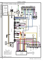
19 INSTALLER CONNECTIONS
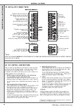
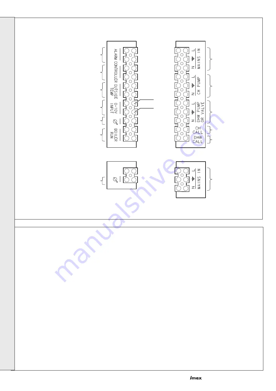
230V AC
permanent
mains supply
230V AC permanent
mains supply
230V AC
output for CH
system pump.
max 1 amp
Optional 230V AC
output for DHW pump
or divertor valve.
max 1 amp.
*
Optional call for CH
Optional call for DHW
im8483
MASTER MODULE
SLAVE MODULE
*
Optional connections for
programmable room stat
and modulating sequencer kits
Optional volt free connections for
boiler alarm during lock out condition.
(Closed circuit during lock out)
Optional connections for outside
temperature sensor kit
*
Optional connections 0-10V
boiler control
Test point for measuring
flame ionisation current using
0-10V DC meter - see Frame 61
Test point for measuring
flame ionisation current using
0-10V DC meter - see Frame 61
Optional volt free connections for
boiler 'run' inidication
(Closed circuit during burner on operation)
0-10V
Ground
*
Note.
BOTH OT CENTERS
MUST
BE CONFIGURED IN ACCORDANCE WITH BOILER CONTROL INPUT OPTION CHOSEN.
(See Frame 22 for details)
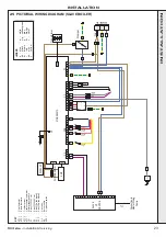
Input terminals are available for connecting a variety of system
controls for central heating demand. Only one method should
be employed on an individual boiler. OT Centers to be
configured in accordance with choice mode (see to Frame 22).
Heating demand can be controlled by:
1. ON/OFF using a 230V switched live to 'CH call' terminal.
(e.g. programmer and/or room thermostat).
A call for heat will cause the boiler to run and maintain a set
flow temperature controlled by parameter 4* (see Frame 31).
Connect switched live to Master Module terminal marked 'CH
CALL'.
2. Programmable Room Thermostat Kit.
The programmable room thermostat kit incorporates a room
temperature sensor and a programmer capable of
controlling the heat output from the boiler to satisfy different
temperature requirements at different time periods. The
addition of an Outside Sensor Kit will enable a weather
compensated flow temperature (see Instructions with kit for
more details).
Connect Programmable Room Thermostat to Master Module
using terminals marked 'CONTROLLER'. Wires have no
polarity and are low voltage control cables.
3. Modulating Sequencer Kit.
A Modulating Sequencer Kit is capable of controlling the
heat demand on up to 5 boilers simultaneously. (See
instructions with kit for more details.)
Connect Modulating Sequencer Kit to Master Module
using terminals marked 'CONTROLLER'. Wires have no
polarity and are low voltage control cables.
4. 0-10V
A call for heat can be generated using a 0-10V input with
the flow temperature setpoint controlled by the voltage
signal. 10V generates a maximum flow temperature top
limited by parameter 4* (see Frame 31).
Connect 0-10V signal to Master Module using terminals
marked '0-10V INPUT'. The ground wire should be
connected to the lower terminal and the 0-10V
modulating signal to the upper terminal.
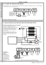
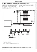
CH Pump
Output terminals marked 'CH PUMP' are provided for a
circulating pump which must be connected to allow the
pump overrun function to operate. A pump requiring more
than 1 amp supply current must be connected via a relay.
20 CH CONTROL CONNECTIONS
* Changes to parameter 4 must be carried out in common to
both Master and Slave Modules.
INST
ALLA
TION


