19
FP14KC-X
JAN 2023
Step 7: Power Unit Electrical Connection
WARNING: Electrical Wiring must comply with local code. Use separate circuit for each power
unit and protect each circuit with time delay fuse. For 208V-230V single phase, use 20 amp fuse.
1)
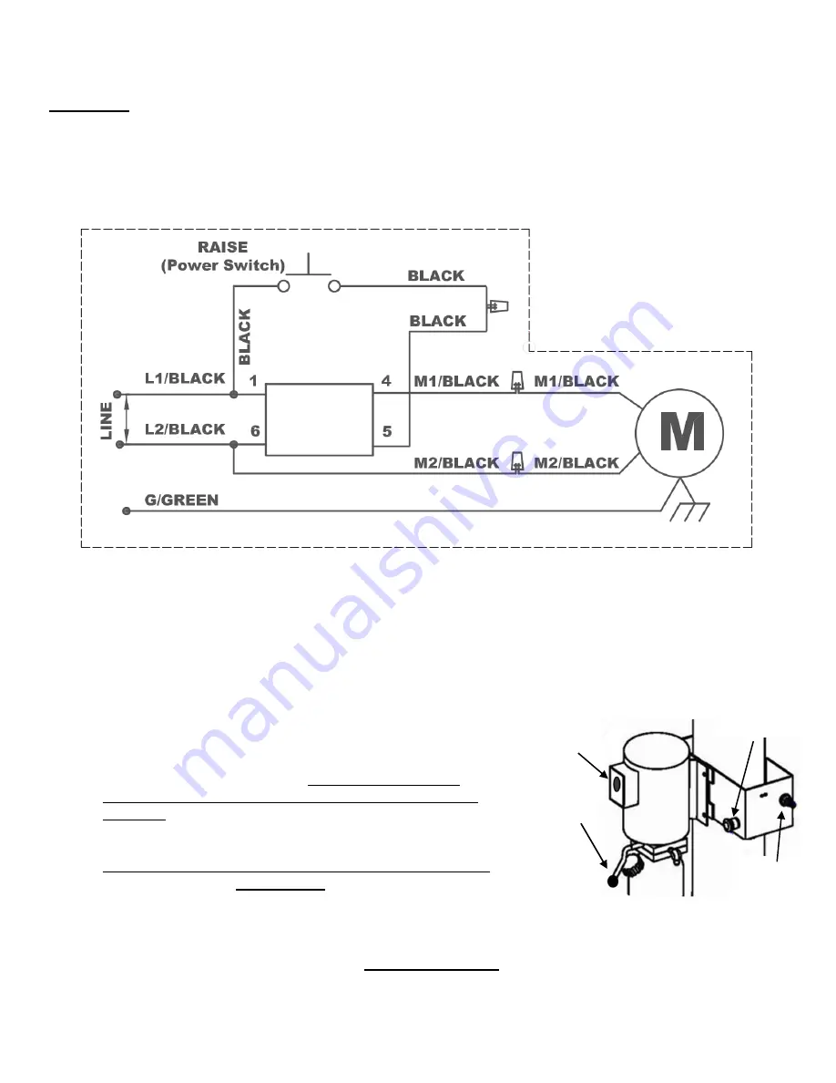
Have a Certified Electrician make the electrical connection from power supply to the power unit. Use
separate circuit for each power unit,
Fig. 29
.
208 - 230VAC, 1PH, 60Hz
Fig. 29
CAUTION!
Never operate the Power Unit in-line voltage less than 208VAC, as motor damage
may occur. Never operate Power Unit with no hydraulic oil, as pump damage may occur.
Step 8: Cycle Testing & Bleeding Hydraulics
CAUTION!
DO NOT place Vehicle on Lift for the following Test Steps.
1) To Cycle Test Lift
, first turn on 220VAC electrical supply
to Power unit and connect shop air to Quick Disconnect
Air Fitting on Control Bracket. Ensure shop air supply
to Air Fitting is between 90 - 115 PSI for proper Latch
operation,
Fig. 30
.
2)
Press the START/UP button on the motor to slightly raise lift, but
only until the steel cables are tensioned in each Post, then release
START/UP button.
IMPORTANT
:
Inspect & confirm the steel cables
are properly engaged in grooves of all cable pulleys
-
Ref. Figs 7 & 8
.
Fig. 30
3) To Bleed Hydraulics
, cycle the lift
‘Up & Down’ fully 2 to 3 times to bleed (remove air) from the hydraulic
system or until the lift lowers smoothly.
OPERATION NOTE: To Lower Lift press the Manual Release
Lever to release hydraulic pressure, while at the same time pressing the ‘Red’ Button on the Air
Valve to release latches allowing lift to lower without engaging Latch Racks,
Fig 30
.
START / UP
Button
Manual
Release Lever
Shop Supply
Air Fitting
Air Valve
Button


