20
FP14KC-X
JAN 2023
4) If Lift Does Not Raise to Full Height
, additional hydraulic fluid may be required. If required, first ensure
the lift is fully lowered, then check fluid level using the Dip Stick on Reservoir,
Fig. 22
.
NOTE
:
Only add
oil in small increments, never adding hydraulic fluid past the Max Fill Line on Drip Stick.
CAUTION!
Only ADD Hydraulic Fluid to Reservoir Tank when the Lift is fully Lowered. Failure
to do so could result in overfilling reservoir tank causing possible damages.
Step 9: Ramp Installation & Leveling Adjustments
1)
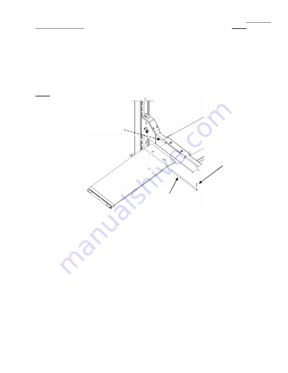
To install the Approach Ramps, it will be best to have the runways raised about 3 to 4 feet. Attach
Ramps to the rear of each Runway using the Ramp Pivot Pin & Cotter Pins, shown in
Fig. 31
.
NOTE:
Ensure Cotter Pins are positioned to the outside of the Runway Pivot Tubes.
Fig. 31
Cable Leveling Adjustment:
2)
Adjust cable(s) with lift fully lowered and with Crossbeams touching Base Plates. Loosen
‘top’ jam nut
and tighten nut on cable stud, on top of Post, until the Crossbeam end is raised 1/4
” (6.4 mm), then back
off nut one turn,
Fig. 14
(Page 14). Retighten
‘top’ jam nut.
3)
Repeat for all four cables.
4)
Confirm runways are horizontally level using either a large level, water gauge or transit.
NOTE:
Runways must be level ‘side to side’ & ‘front to rear’. Max tolerance cannot exceed 9/16”.
Final Leveling Adjustments with Vehicle:
5)
Load a typical vehicle on lift, ensuring to apply Wheel Chocks behind vehicle front wheels, after loading.
6)
Raise lift as high as it will travel (full height). You should hear the locking latches
‘click’ through all 18ea
latch slots simultaneously or very close to each other.
7)
Lower lift onto the top latch position.
Runway
(Rear)
Cotter Pin
Approach
Ramp
Ramp
Pivot Pin
Runway
Pivot Tube


