59
F
AUL
T FINDING F
AUL
T FINDING F
AUL
T FINDING F
AUL
T FINDING F
AUL
T FINDING
Installation and Servicing
SECTION 4 - FAULT FINDING
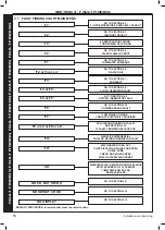
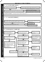
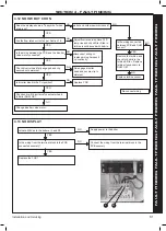
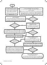
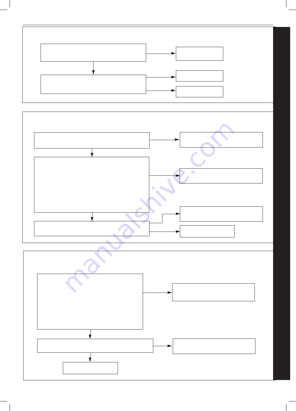
4.7 ‘F3’ - FAN FAULT
Does the wiring from the Fan to the PCB have
secure connections at both ends and has not
deteriorated? Does the wiring have continuity?
YES
Rectify Wiring &
connections
Is there 230Vac at the Blue and Brown connections
to the 3 way connection on the Fan?
NO
Replace PCB
Replace Fan
NO
YES
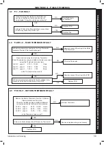
4.8 ‘F4 OR L4’ - FLOW THERMISTOR FAULT
Disconnect the wiring from the Flow Thermistor
Check the resistance using a suitable multimeter connected
across the Thermistor’s terminal pins.
At 25
o
C expect
9,700 - 10,300
Ohms
At 60
o
C expect
2,400 - 2,600
Ohms
At 85
o
C expect
1,000 - 1,100
Ohms
Is the Thermistor value correct?
YES
Is the wiring securely connected to the low voltage 6 way
connector at the front left hand side of the PCB?
YES
Replace PCB
Fit a new Thermistor
NO
Securely connect the wiring to the PCB
Is the wiring securely connected to the Flow Thermistor
(located in the top of the Heat Exchanger?)
YES
NO
Securely connect the wiring to the Water
Flow Thermistor
NO
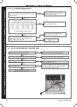
4.9 ‘F5 OR L5’ - RETURN THERMISTOR FAULT
Remove the Return Thermistor from the CH Return
Pipe and disconnect the wires.
Check the resistance using a suitable multimeter
connected across the thermistor’s terminal pins.
At 25
o
C expect
9,700 - 10,300
Ohms
At 60
o
C expect
2,400 - 2,600 Ohms
At 85
o
C expect
1,000 - 1,100 Ohms
Is the Thermistor value correct?
YES
Is there continuity between the PCB and the Thermistor?
YES
Replace PCB
Fit a new Thermistor
NO
Check and replace wiring as necessary
NO
Summary of Contents for INDEPENDENT COMBI 24
Page 4: ...4 Installation and Servicing...
Page 6: ...6 Installation and Servicing...
Page 63: ...63 Installation and Servicing...
Page 64: ......
Page 70: ...70 Installation and Servicing...
Page 71: ...71 Installation and Servicing...

