background image

29

Mexico Slimline CF 3/40 & 3/50 - 

Installation

SERVICING

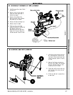
43 MAIN BURNER REPLACEMENT

1.

Lift off lower front panel and remove the
grille assembly.  Undo the gas cock
union. Remove the burner and controls
assembly. Refer to Frames 27 & 28.

2.

Unscrew the burner injector from the
manifold.

3.

Fit the new injector, using an approved
jointing compound, and re-assemble in
reverse order.

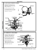
44 MAIN BURNER INJECTOR REPLACEMENT

SER

VICING

1.

Lift off lower front panel and remove the  grille assembly.
Undo the gas cock union. Remove the burner and controls
assembly. Refer to Frames 27 & 28.
Undo the 2 wing nuts and remove the burner and controls
assembly.

2.

Undo the nut securing the pilot bracket to the main burner
and remove the pilot bracket.

3.

Remove the 4 nuts and washers securing the main burner to
the front plate and gas manifold.  Withdraw the burner.

4.

Remove the nut securing the burner baffle to the burner.

5.

Fit the new burner and re-assemble in reverse order, taking
care not to damage the main burner injector which is
screwed into the end of the gas manifold.

Summary of Contents for Mexico Slimline CF3/40

Page 1: ......

Page 2: ...mline models at only 250mm wide and 8 propane Super models Option kit availability includes an easy to use programmer kit available on all models an overheat thermostat kit for all models and a pump k...

Page 3: ...ing balanced flue terminal kg lb 94 207 Boiler Size Height mm in 850 33 5 Width mm in 255 10 0 Depth mm in 535 21 0 Gas Type Natural 2 H Gas Supply Pressure 20 mb GENERAL Table 1 General Data Table 2...

Page 4: ...ssembly Exploded view 9 Boiler Clearances 6 Burner Assembly Exploded view 34 Electrical Connections 15 Electrical Diagrams 15 Electrical Supply 8 Fault Finding 31 Flue Connection 15 Flue Installation...

Page 5: ...misers etc are directly connected to these appliances unless covered by these Installation and Servicing Instructions or otherwise recommended by Caradon Plumbing Limited in writing If in doubt please...

Page 6: ...ber Framed Buildings If the boiler is to be fitted in a timber framed building it should be fitted in accordance with the Institute of Gas Engineering document IGE UP 7 1998 Compartment Installations...

Page 7: ...ations of BS 5440 1 The following notes are intended for general guidance 1 The cross sectional area of the flue serving the boiler MUST NOT be less than the area of the flue outlet of the boiler If f...

Page 8: ...system should be in accordance with BS 6798 and in addition with BS 5449 1 for smallbore and microbore systems The domestic hot water system if applicable should be in accordance with the relevant re...

Page 9: ...N INSTALLATION 3 BOILER ASSEMBLY Exploded View 6 Front plate assembly 9 Main burner 15 Gas valve 17 Piezo unit LEGEND 1 Heat exchanger 2 Boiler feet assembly 3 Thermostat pocket 4 Cleanout cover 21 Ga...

Page 10: ...these Installation and Servicing Instructions z User s Instructions INSTALLATION INSTALLATION To avoid damage to the boiler casing it is recommended that the casing is removed BEFORE the boiler body i...

Page 11: ...panel by lowering and pulling it forward In order to remove the control panel entirely the TTB thermostat has to be carefully released 5 Remove the 2 screws securing the top panel to the side 6 Draw...

Page 12: ...ssure of 20 mbar 8 in w g MUST be available at the boiler inlet with the boiler operating 2 Extend a gas supply pipe NOT LESS THAN 15mm 1 2 OD to the boiler and connect to the gas cock situated at the...

Page 13: ...n Frame 1 2 The boiler is assumed to be the highest point of the circulating system 3 The circulating pump is positioned on the FLOW and the vertical distance between the pump and feed expansion tank...

Page 14: ...ven in Frame 1 but ONLY those shown should be used 2 The use of a cylinder thermostat is recommended This will prevent excessive DHW temperatures and thus reduce gas consumption 3 The schematic pipewo...

Page 15: ...ble NOT LESS than 0 75 mm2 24 x 0 2 mm to BS 6500 Table 16 14 INTERNAL WIRING Flow and pictorial wiring diagrams are shown in Frames 15 and 16 A schematic wiring diagram is included in the Lighting In...

Page 16: ...ot arise providing the following directions are observed 1 Controls that switch the system ON and OFF e g a time switch MUST be wired in series in the live mains lead to the boiler 2 Controls that ove...

Page 17: ...oiler thermostat to maximum 4 Switchmaster Autozone has grey and orange auxiliary switch leads but the GREY NOT the orange wire must be connected to the incoming live supply LEGEND b blue bk black or...

Page 18: ...stat should be wired into the system This is usually done at the programmer in which case the programme selector switches are set to OFF and all other controls MUST be left in the running position The...

Page 19: ...ion on the gas service cock on the boiler and purging until gas is detected 3 Retighten the union and check for gas soundness WARNING Whilst effecting the required gas soundness test and purging air f...

Page 20: ...nvelops the tip of the thermocouple and is approximately 25mm 1 long The pilot flame is factory set and no adjustment is possible 8 Switch the boiler thermostat control knob H to position 6 and check...

Page 21: ...should be fully explained to the householder to ensure the greatest possible fuel economy consistent with household requirements of both heating and hot water consumption Advise the User of the preca...

Page 22: ...nstalled in a compartment check that the ventilation areas are clear The servicing procedures are covered more fully in Frames 28 to 32 and MUST be carried out in sequence WARNING Always turn OFF the...

Page 23: ...burner head ensuring that the flame ports are unobstructed and remove any debris that may have collected Note Brushes with metallic bristles MUST NOT be used 3 Remove the main burner injector Check c...

Page 24: ...glass in the front plate clean or renew as necessary 6 Renew any damaged or deteriorating front plate gasket 7 Refit the burner and controls assembly 8 Reconnect the gas service cock 9 Refit the grill...

Page 25: ...studs on the gas valve and withdraw the unit as shown 3 Fit the new unit and reassemble in reverse order 35 PIEZO UNIT REPLACEMENT 36 PILOT BURNER REPLACEMENT 1 Lift off lower front panel and remove...

Page 26: ...e electrical connections from the gas valve 4 Unscrew the 2 screws and pull down the control panel so that the 2 tabs clear the top panel 5 Remove the bottom screw and remove the cover from the contro...

Page 27: ...n the thermostat sits in the small hole adjacent to the main fixing hole and reassemble in reverse order 1 Lift off lower front panel and remove the grille assembly Undo the gas cock union Remove the...

Page 28: ...nut and withdraw the electrode upward Re assemble in reverse order 42 THERMOCOUPLE REPLACEMENT 1 Lift off lower front panel and remove the grille assembly Undo the gas cock union Remove the burner an...

Page 29: ...off lower front panel and remove the grille assembly Undo the gas cock union Remove the burner and controls assembly Refer to Frames 27 28 Undo the 2 wing nuts and remove the burner and controls asse...

Page 30: ...nd lead and re assemble in reverse order ensuring that all electrical connections are correctly remade and cables secured 1 Lift off lower front panel and remove the grille assembly Undo the gas cock...

Page 31: ...plied NO NO Allow time to purge any air present by increasing the pilot gas rate done by adjusting the screw Check that the gas control knob is being pressed fully in that there is gas pressure at the...

Page 32: ...038 19 E01 412 HT lead 460mm long 1 052 888 20 390 039 Thermocouple HONEYWELL Q 309 A 2739 600mm lg 1 000 842 25 Thermostat RANCO K36 P1354 1 151 903 26 308 557 Thermostat knob 1 111 904 41 E01 415 Fl...

Page 33: ...33 Mexico Slimline CF 3 40 3 50 Installation LIST OF PARTS 50 SHORT PARTS...

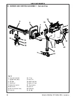
Page 34: ...T OF PARTS Legend 6 Front plate assembly 7 Sightglass assembly 8 Pilot pipe 9 Main burner 11 Main burner injector 12 Pilot burner 14 Pilot burner bracket assy 15 Gas valve 16 O ring 17 Piezo unit 18 I...

Page 35: ...40 3 50 Installation LIST OF PARTS 52 CONTROL BOX ASSEMBLY Exploded View Legend 23 Control panel complete 24 Control box 25 Control thermostat 26 Thermostat knob 27 Controls panel 28 Magnetic strip 2...

Page 36: ...40 3 50 Installation 53 BOILER CASING ASSEMBLY LIST OF PARTS Legend 22 Casing complete 23 Control panel complete 32 L H side panel 33 R H side panel 34 Top panel 35 Grille panel 36 Front lower panel 3...

Page 37: ...37 Mexico Slimline CF 3 40 3 50 Installation...

Page 38: ...Training Caradon Plumbing Limited pursues a policy of continuing improvement in the design and performance of its products The right is therefore reserved to vary specification without notice THIS SY...

Page 39: ...e ll be giving away a free boiler for the five best ideas every year to be selected by our Technical Director Please complete this form using extra sheets if required and post it or fax it to us on 01...

Page 40: ...deal domestic boiler range The Ideal Householders Guide to assist the installer when presenting to his her customers Technical manuals required The Ideal C class combi boiler The Ideal Classic wall hu...

Reviews: