41
Response FF80
- Installation
SER
VICING
SERVICING
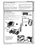
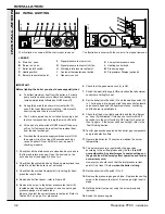
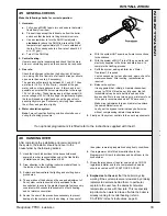
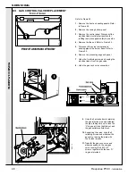
64 GAS CONTROL VALVE REPLACEMENT - continued
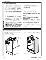
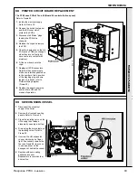
65 WATER PRESSURE GAUGE
5.
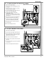
Disconnect the capillary at the
CH flow pipe boss.
6.
Squeeze the tabs to release the
pressure gauge.
7.
Fit the replacement gauge and
reassemble in reverse order.
8.
Close all drain cocks and open
both isolating valves.
9.
Fit the filling loop. Fill the boiler
with water and pressure to 1 bar
(as appropriate). Reconnect
services.
10.
After satisfactory test firing and
removal of air from the system,
remove the filling loop.
1.
Disconnect the electrical supply to the boiler.
2.
Remove the bottom panel.
3.
Remove the controls panel. Swing the panel upside down
and fix with the long screws.
4.
Close the isolating valves on CH flow/return at base of
boiler then, release CH system pressure by opening one of
the CH drain cocks on the isolating valves.
It is not advisable to release system pressure using the
safety valve.
12.
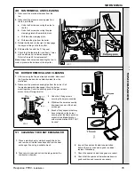
Offer the gas valve to the plate, making sure that the
stud feeds in to the corresponding hole the rear of the
metal plate.
Fix the gas valve and plate in place, using the 4 M5 x
10 pozi pan screws.
Refit the manifold block and injector pipe, checking that
gasket and 'O' ring are undamaged.
13.
Check the operation of the new gas valve.
14.
Operate the boiler for at 10 minutes at full rate and
check the burner pressure against the value shown on
the date plate for CH or HW as appropriate.
15.
Fit the new gas valve in reverse order, ensuring that the
gas injection pipe 'O' ring seal is refitted.
16.
Check the operation of the new gas valve.
17.
Operate the boiler on HW for at least 10 minutes at full
rate and check the burner pressure against the value
shown on the data plate or in Table 3.


