45
Response FF80
- Installation
71 HEAT EXCHANGER REPLACEMENT
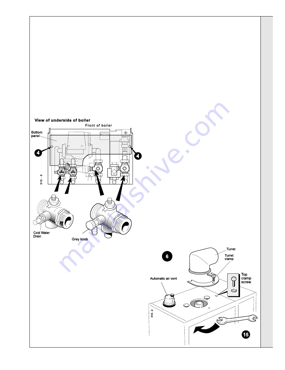
SERVICING
SER
VICING
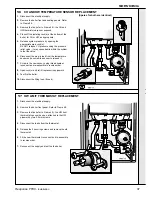
withdraw the assembly downwards, taking care not to
damage the electrodes - refer to Frame 61.
12
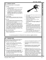
. Unplug the electrical leads from both CH and HW
temperature sensors and disconnect the leads from the HW
overheat thermostat. Unscrew the CH temperature sensor
and remove it, to avoid damage to it - refer to Frames 56
and 57.
13.
Loosen the top and bottom connections on the 22mm CH
pipes to the heat exchanger.
14
. Loosen the bulkhead connectors at the lower end of the
15mm HW pipes, together with the hexagon socket screws
retaining the upper ends of these pipes. The inlet pipe can
now be swung round and withdrawn, complete with HW
expansion vessel.
The straight outlet pipe cannot be removed until later - see
paragraph below.
15
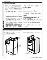
. Unscrew the automatic air vent on the top of the heat
exchanger. This should be done inside the jacket in order
not to unscrew merely the top off the air vent.
16.
Next remove the 2 screws securing the heat exchanger
from below, together with the top clamp screw.
17.
The heat exchanger is now free and should be supported
whilst removing the HW outlet pipe.
18.
Remove heat exchanger from the boiler.
19.
Re-assemble in reverse order, using new gaskets as
appropriate.
20.
Before refitting the fan, check that the wires have been
reconnected to the CH sensor (mauve pair), HW sensor
(grey), overheat 'stat (black) and flame detection electrode
(yellow).
21.
When re-assembly is complete, fit the filling loop, close all
drain points, open all isolating valves and ensure that the
boiler is filled, vented of air and pressurised before
attempting to fire it.
22
. After a satisfactory test firing, remove the filling loop (this is
a requirement of the water bylaws).
6.
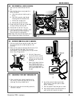
While the boiler is draining, release the turret clamp on top
of the boiler, together with the screw securing the turret to
the flue pipe. Remove the turret.
7.
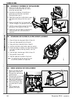
Disconnect the fan pressure sensing pipe by removing the 2
screws at the fan end and the screws of the securing plate
at the gas valve end. Remove the pipe- refer to Frame 66.
8.
Unplug the wiring harness from the fan. Release the clip
securing the fan and rotate the fan towards you until it is
free of its bayonet mounting socket (the fan may
alternatively be removed complete with harness) - refer to
Frame 66.
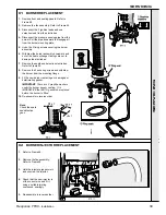
9.
The second pressure sensing pipe, which is connected via
an 'O' ring seal to the burner base may now be carefully
withdrawn downwards.
10.
Disconnect the spark electrode leads and the flame sensing
electrode lead at the burner base - refer to Frame 59.
11.
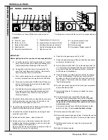
Remove the 3 screws securing the burner assembly and
WARNING.
This will necessitate disconnection of all services,
including the flue turret.
Refer also to Frame 7 - 'Boiler Exploded View'.
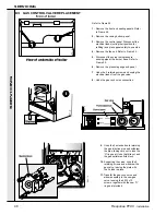
1.
Isolate the electrical supply to the boiler.
2.
Isolate the water and gas supplies by closing all 4 cocks
below the boiler.
3.
Remove the boiler front panel and inner sealing panel -
refer to Frame 48.
4.
Remove the bottom panel.
5.
Attach drain pipes to the 4 boiler drain points, one on each
isolating valve. Open the CH drains by turning the grey
knobs and the HW drains by slackening the drain nipple.
Note the marking on the bottom of the valves. Refer to
Frame 52


