33
Response SE Combi -
Installation
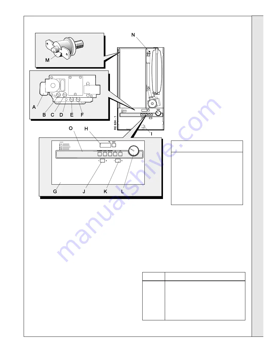
45 INITIAL LIGHTING
INSTALLATION
1.
Check that the system has been filled and that the boiler
is not airlocked. Ensure the automatic air vent screw is
open (N)
2.
Check that all the drain cocks are closed and that the
CH and DHW isolating valves are OPEN.
3.
Check that the electrical supply is OFF.
4.
Check that the gas service cock (
I
) is OPEN.
5.
Remove screw and swing the control panel down .
6.
Remove the screw in the burner pressure test point (C)
and connect a gas pressure gauge via a flexible tube.
7.
Swing the control panel into its working position.
8.
Ensure that the external CH controls are calling for heat
and set the switch (K) to ON.
LEGEND
A.
Gas control valve
B.
Inlet pressure test point
C.
Burner pressure test point
D.
Offset adjuster (sealed)
E.
Fan pressure test point (Hi)
F.
Fan pressure test point (Lo)
G.
Control panel
H.
Display board
I.
Gas service cock (hidden)
J.
On/Off switch
K.
Central heating (CH) on/off switch
L.
Central heating pressure gauge
M.
Flue thermostat (behind sealing panel)
N.
Automatic air vent
O.
Cover plate
Control panel
:
contains digital display and 6 buttons
Button
Function
RESET
Reset of system
MODE
Mode of display
STEP
Step within the mode
STORE
Storage of setting
UP(+)
Increase of setting
DOWN (-)
Decrease of setting
9.
Switch the electricity supply ON.
10.
Set the switch (J) to ON.
11.
The boiler ignition sequence should now start.
Note.
A self check cycle will take place whenever the
RESET button on the control panel is pressed, and also
once every 24 hours without a call for heat, to ensure
movement of the components once a day.
Sequence
Boiler Status
0
No heat request.
1
Fan pre-purge for 8 seconds.
2
Gas valve opens and spark commences.
3
Burner ignition and flame detection (CH).
4
Burner ignition and flame detection (DHW)
INST
ALLA
TION


