background image

39

Response SE Combi - 

Installation

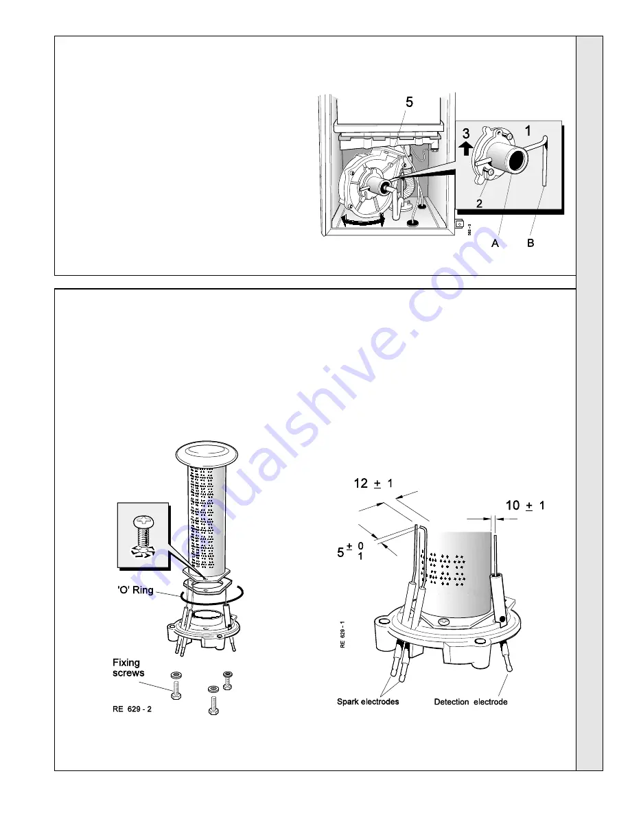
55 FAN REMOVAL AND CLEANING

SERVICING

4.

Inspect the spark and detection electrodes.
Ensure that they are clean and in good condition -
replace if necessary.

5.

Check that the spark and electrode gaps are
correct.

6.

Check that the spark and detection leads are in
good condition and renew as necessary.

Legend

A

Venturi

B

Sensing pipe

1.

Undo the fan inlet venturi top securing screw.

2.

Slacken the other 2 securing screws.

3.

Slide the venturi upward to disengage the sensing pipe
from the gas manifold.

4.

Withdraw the venturi, complete with sensing pipe, from the
boiler.

5.

Depress the retaining clip and rotate the fan to the right to
disengage the bayonet fixing on the fan outlet.

6.

Draw the fan forward and unplug the electrical lead from
the motor.

7.

Withdraw the fan from the boiler.

Check that the fan impeller runs freely.  Clean with a soft
brush and renew as necessary.

Note.


Always take care when handling the fan, in order to

preserve the balance of the impeller.

56 BURNER REMOVAL AND CLEANING

1.

Disconnect the ignition and detection leads from the electrodes.

2.

Undo the 3 fixing screws securing the burner assembly.

Withdraw the burner assembly downward and out of the heat
exchanger.

3.

Brush off any deposits that may have collected on the burner,
ensuring that the flame ports are unobstructed.

 Note.


Brushes

with metallic bristles must NOT be used.

SER

VICING

Summary of Contents for Response SE

Page 1: ......

Page 2: ...ded vertical flue connection not available for HEES Flue Elbow Kits 90 o and 45 o 2 per pack Pack S Siphon Kit Refer to the separate fitting instructions supplied with each kit RESPONSE SE Natural gas...

Page 3: ...c value a FOR L S divide the gross heat input kW by the gross C V of the gas MJ m3 b FOR FT 3 H divide the gross heat input Btu h by the gross C V of the gas Btu ft3 Table 2 Performance Data Central H...

Page 4: ...W is drawn off The full output from the boiler is then directed via the diverter valve to the calorifier to supply a maximum DHW draw off of 10 l min at 35 o C temperature rise 1 BOILER WATER CIRCUIT...

Page 5: ...The boiler must be installed on a flat and vertical wall capable of adequately supporting the weight of the boiler and any ancillary equipment The boiler may be fitted on a combustible wall and insul...

Page 6: ...microbore systems BS 5449 The domestic hot water system should be in accordance with BS 5546 and BS 6700 Copper tubing to BS 2871 1 is recommended for water carrying pipework and MUST be used for pip...

Page 7: ...ECTIONS Notes 1 It is most important that the correct concentration of the water treatment product is maintained in accordance with the manufacturers instruction 2 If the boiler is installed in an exi...

Page 8: ...installed in a room containing a bath or shower then the appliance and any electrical switch or appliance control utilising mains electricity should be so situated that it cannot be touched by a perso...

Page 9: ...loss from the system either a From a manually filled make up vessel with a readily visible water level The vessel should be mounted at least 150mm above the highest point of the system and be connecte...

Page 10: ...ion of Domestic Gas Condensing Boilers 1989 A condensate drain is provided on the boiler This drain must be connected to a drainage point on site All pipework and fittings in the condensate drainage s...

Page 11: ...ose 35 Heat exchanger 48 Prepiping frame 50 Control panel 72 Gas injection pipe 18 Automatic air vent 19 Fan pressure sensing pipe 22 CH return pipe 24 Pump inlet pipe 25 Boiler return pipe 26 Boiler...

Page 12: ...z These Installation and Servicing Instructions z User s Instructions z Stand off brackets optional use 1 pair z Concealment panels optional use 1 pair z Inner flue seal Concealment panels The boiler...

Page 13: ...ue outlet 1000 mm long Refer to Flue Extension Ducts Vertical Flue see optional extras IMPORTANT The boiler MUST be installed in a vertical position Note The flue duct MUST be inclined at 2 50 to the...

Page 14: ...eness by hanging a plumbline as shown 3 Mark onto the wall the following a The 4 wall mounting plate screw positions b The position of the flue duct Mark the centre of the hole as well as the circumfe...

Page 15: ...utside of the building does not cause damage or personal injury 14 FITTING THE PIPING FRAME Fit the wall mounting frame either a Directly to the wall z z z z z Insert wall plugs z z z z z Put the scre...

Page 16: ...b 8 w g must be available at the boiler inlet with the boiler firing at full DHW output Note Do not subject any of the isolating valves to heat as the seals may be damaged 16 GAS CONNECTION Bottom and...

Page 17: ...he boiler 18 CUTTING THE FLUE Rear Flue Length of 114 to 580mm Note If the optional standoff bracket kit is used it is essential that 80 mm is added to the measured wall thickness when marking the flu...

Page 18: ...the boiler by pouring a cupful of water into the flue outlet A 1 Insert the flue assembly through the prepared hole in the wall far enough to allow the rubber seal to unfold completely and form an ad...

Page 19: ...unting plate screw positions b The position of the flue duct Mark the centre of the hole as well as the circumference Note Allow for stand off brackets if being used Use the table on the wall mounting...

Page 20: ...mmed around the groove provided The terminal wall plate need not be fitted 24 FITTING THE PIPING FRAME Fit the wall mounting frame either a Directly to the wall z z z z z Insert wall plugs z z z z z P...

Page 21: ...of not less than 22mm O D copper or 3 4 BSP iron to the boiler A working gas pressure of 20mbr 8 w g must be available at the boiler inlet with the boiler firing at full DHW output Bottom and top conn...

Page 22: ...lows a Measure and note the wall thickness X b Add dimension H measured in Frame 22 c For right hand side flue add 188mm 7 3 8 d For left hand side flue add 61mm 2 3 8 i e X H 188mm 7 3 8 for RHS X H...

Page 23: ...d hole in the wall far enough to allow the rubber seal to unfold completely and form an adequate seal on the outside wall 2 Pull the flue back and locate the flue turret on the top of the boiler ensur...

Page 24: ...ework must be arranged so that obstruction e g through freezing of external drainage pipe does not give rise to spillage within the dwelling Excessive external pipe runs should be avoided in order to...

Page 25: ...discharge pipe should be such that any discharge of water or steam does not create a hazard 4 Use the 900 compression elbow so the pipe is directed towards the rear 33 SAFETY VALVE DRAIN 35 FLUE EXTEN...

Page 26: ...lue extension duct onto the outer air duct 5 Drill one 3 2mm 1 8 dia hole through the outer air duct Do not drill the inner flue duct 6 Insert the self tapping screw provided to fix the air duct in po...

Page 27: ...me 4 INSTALLATION Front elevation layout of boiler components control panel open Legend A Boiler heat exchanger B Gas valve C Safety valve D DHW plate heat exchanger E Condensate safety drains F CH fl...

Page 28: ...lling there may be a slight water leak from the vent therefore electrical connections should be protected c Ensure that the pump is free to rotate i Remove the vent plug ii Using a screwdriver rotate...

Page 29: ...mplete isolation of the electrical supply such as a double pole switch having a 3mm 1 8 contact separation in both poles or a plug and socket serving only the boiler and system controls The means of i...

Page 30: ...r otherwise the boiler can be left live even when the boiler isolating switch is off Using a two channel programmer will disable the heating switch 3 Room Thermostat It is recommended to use a room th...

Page 31: ...31 Response SE Combi Installation INSTALLATION 42 PICTORIAL WIRING DIAGRAM Legend b blue bk black br brown gy grey p purple or orange pk pink r red w white y yellow g y green yellow INSTALLATION...

Page 32: ...earth continuity polarity resistance to earth and short circuit using a suitable test meter B Gas Installation 1 The whole of the gas installation including the meter should be inspected and tested f...

Page 33: ...re test point Hi F Fan pressure test point Lo G Control panel H Display board I Gas service cock hidden J On Off switch K Central heating CH on off switch L Central heating pressure gauge M Flue therm...

Page 34: ...n and ensure that water flows freely from them 2 Close all taps except the furthest one from the boiler and check that the boiler is firing at maximum rate 3 Release the boiler bottom panel 4 Turn the...

Page 35: ...ure to the design requirement 6 Balance the system Refer to Frame 6 7 Check the condensate drain for leaks and check that it is discharging correctly 8 Finally set the controls to the User s requireme...

Page 36: ...e STEP button c Reset the temperature to the required value by pressing and buttons d Store the new value by pressing the STORE button The display should flash twice e To return the control to the nor...

Page 37: ...umption Advise the User of the precautions necessary to prevent damage to the system and to the building in the event of the system remaining inoperative during frosty conditions 5 Explain the functio...

Page 38: ...appropriate z Check the sealing panel is correctly refitted ensuring that a good seal is made 53 CASING REMOVAL 54 BOILER SEALING PANEL REMOVAL 1 Release the 2 retaining clips 2 Swing the panel open t...

Page 39: ...r 5 Depress the retaining clip and rotate the fan to the right to disengage the bayonet fixing on the fan outlet 6 Draw the fan forward and unplug the electrical lead from the motor 7 Withdraw the fan...

Page 40: ...imilar beneath the boiler and remove all visible loose deposits from the heat exchanger fins using a suitable brush 2 Take care to clean debris from the ledge inside the combustion chamber 1 Pull off...

Page 41: ...E BOILER MUST NOT BE OPERATED IF THE SEALING PANEL IS NOT FITTED Note In order to replace components in Frames 75 to 85 it is necessary to drain the boiler Refer to Frame 72 1 Refer to Frame 60 2 Remo...

Page 42: ...R REPLACEMENT Legend A Burner B Gasket C Burner mounting flange D O ring seal 1 Refer to Frame 60 2 Remove the boiler casing Refer to Frame 53 3 Remove the boiler sealing panel Refer to Frame 54 4 Rem...

Page 43: ...lectrode 1 Refer to Frame 60 2 Remove the boiler casing Refer to Frame 53 3 Remove the boiler sealing panel Refer to Frame 54 4 Unscrew the injector from the injection pipe 5 Fit the new injector usin...

Page 44: ...complete with mounting brackets and gas inlet pipe 10 Transfer the mounting brackets and sensing pipes to the new valve renewing any damaged or deteriorating sealing gaskets 11 Transfer the gas inlet...

Page 45: ...he display board Ensure that the control unit is the correct one for the boiler 7 Unplug the spark and detector leads 8 Undo the 4 securing screws and withdraw the control unit from the panel 9 Fit th...

Page 46: ...e body 6 Fit the new actuator and re assemble in reverse order 7 Check the operation of the new actuator 72 DRAINING THE BOILER IMPORTANT In order to replace the components in Frames 73 to 85 it is ne...

Page 47: ...tacle 6 Pull off the trap from the bottom of the boiler 7 Withdraw the trap from the boiler 8 Fit the new trap and re assemble in reverse order 74 DHW THERMISTOR SENSOR REPLACEMENT 1 Refer to Frame 60...

Page 48: ...ashers provided and re assemble in reverse order 9 Check the operation of the new valve 75 CH THERMISTOR SENSOR REPLACEMENT Note There are 2 control thermistors one on the boiler flow boss and one on...

Page 49: ...sly b The gauge is correctly orientated within the panel 1 Refer to Frame 60 2 Remove the boiler casing Refer to Frame 53 3 Drain the boiler Refer to Frame 72 4 Close the DHW inlet isolating valve and...

Page 50: ...er 9 Fit the new pump and re assemble in reverse order ensuring that a The new seals provided are fitted b The electrical connections are correctly remade c The pump selector switch is set at position...

Page 51: ...complete with O ring provided and re assemble in reverse order IMPORTANT Ensure that the vent cap is loose A 1 Refer to Frame 60 2 Remove the boiler casing Refer to Frame 53 3 Remove the boiler seali...

Page 52: ...ols with a waterproof sheet or plastic bag 1 Refer to Frame 60 2 Remove the boiler casing Refer to Frame 53 3 Remove the boiler sealing panel Refer to Frame 54 4 Drain the boiler Refer to Frame 72 5 D...

Page 53: ...g the heat exchanger from below withdraw the bosses from the flow and return tappings Check the O ring seals for damage and replace if necessary 22 Lower the heat exchanger to disengage from the flue...

Page 54: ...uest 1 Fan pre purge 2 Ignition 3 Burner on CH 4 Burner on DHW 5 Airflow switch not correct not applicable 6 Burner off in CH mode flow temperature T1 5 o C above set flow temperature Tset 7 Pump over...

Page 55: ...out 4 05 4 06 4 4 07 4 10 4 11 4 13 4 14 4 15 4 16 4 17 4 24 Flow and return sensors NTC1 and NTC2 reversed 4 26 Minimum gas pressure 4 30 Maximum difference between T1 and T2 exceeded 4 31 NTC1 short...

Page 56: ...9 8 Fan speed control board 1 139 950 9 E00 050 Water pressure switch SIT 1 075 176 10 CH flow and return thermistor sensors and DHW thermistor sensors CROSSLAND COMPONENTS 3 150 260 11 E00 055 Pressu...

Page 57: ...57 Response SE Combi Installation 89 SHORT PARTS LIST SHORT LIST OF PARTS...

Page 58: ...ition electrode 13 Fan 14 Fan inlet venturi 19 Fan pressure sensing pipe 42 O ring 43 O ring 44 O ring 45 Gasket rubber 46 Gasket Cork 54 EV1 solenoid 55 EV2 solenoid 60 O ring 61 Burner gasket 70 Gas...

Page 59: ...e SE Combi Installation 91 CONTROL PANEL ASSEMBLY Exploded View Legend 6 Gasmodul control 7 Display board 8 Fan speed control board 11 CH pressure gauge 12 Rocker switch 50 Control panel 58 Relay LIST...

Page 60: ...Office National Avenue Kingston upon Hull HU5 4JN A subsidiary of Caradon plc October 2000 151396 A07 The code of practice for the installation commissioning servicing of central heating systems Ideal...

Reviews: