IDEATEC S.A. - Z.I. de Noville-les-Bois - rue Léopold Génicot 19A - 5380 Fernelmont, Belgium - Tel: +32(0)81 42 00 10 - Fax: +32(0)81 57 91 70 - E-mail: info@ideatec.be
User’s guide DLC4000/DLC8000 -
Doc. V2.1 - Firmware V3.1
Page 13
Identification des éléments
Description des éléments
Description du produit
11.
&
Fig.1
CONFIGURATION MODE 1
CONFIGURATION MODE 2
Fig.2
DLC4000 CONSOLE
DLC8000 CONSOLE
Example 1
Example 2
11.4.2.
Conditions for configuration.
The console must be connected correctly to the power module using only the RJ45 provided from the manufacturer
(see page 4). The power module must be powered by 10 to 28,5VDC.
Once the assembly is powered, the console sounds two brief warnings and its backlight is activated. From this
moment, the configuration mode is accessible for five minutes, after which you will not be able to access it. If, after this
time, you need to access the configuration again, disconnect the power module from the power supply for ± 3 seconds,
and reconnect it. For this, it is always recommended to remove the positive wire from the power supply and to leave
the negative one.
11.4.3.
To enter in configuration mode.
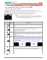
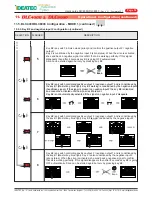
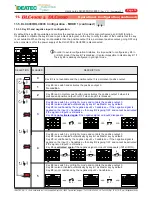
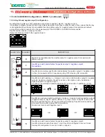
There are two configuration modes for DLC4000/DLC8000. Mode 1 allows you to configure the keys 1 to keys 8 and
inputs.
Mode 2 allows you to configure conditions and simulation for arrow stick functions and standby modes.
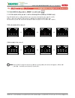
Connect power module on power supply and keep keys B1 and B3 for mode 1 pressed (Fig.1) or keys B2 and B4
pressed for mode 2 (Fig.2) until the console emits a repetitive beep, then release them . You are in configuration mode
then you have the possibility to change the property of each key of the console.
11.4. Before to configure the DLC4000 or the DLC8000
i
In order to make the configuration easier, it is recommended that you choose and place all pictograms on
the console correctly. Additionally, touching the keys without placing the pictograms first may prevent
proper adherence.
11.4.1.
Selection and placement of pictograms on the keys
A collection of more than 88 pictograms is provided with the console. Select the symbols that match your application
and place them on each cavity. Never touch the adhesive part with your fingers. If one or more keys will not be used, it
is recommended that you place black adhesives provided for this purpose.
Operation & Configuration (continued)
ATTENTION
FOR REASONS OF SAFETY, THE
CONFIGURATION IS ONLY
ACCESSIBLE WITHIN THE FIRST
FIVE MINUTES. IF NO ACTION IS
TAKEN DURING ONE MINUTE,
THE SYSTEM EXITS
CONFIGURATION
AUTOMATICALLY. HOWEVER,
ANY CHANGES MADE ARE
SAVED.


