background image

IDEATEC S.A. - Z.I. de Noville-les-Bois - rue Léopold Génicot 19A - 5380 Fernelmont, Belgium - Tel: +32(0)81 42 00 10 - Fax: +32(0)81 57 91 70 - E-mail: info@ideatec.be

User’s guide DLC4000/DLC8000 - 

Doc. V2.1 - Firmware V3.1

1.

2.

Page 2

0.34  

22


X


X


X

  X

 X


X


X


X


X


X


X


X


X


X


X


X

X

X

0.5  

20


X


X


X

  X

 X


X


X


X


X


X


X


X


X


X


X


X

X

X

0.75  

18


X


X


X

  X

 X


X


X


X


X


X


X


X


X


X


X


X

X

X

1.5  

16


X


X


X

  X

 X


X


X


X


X


X


X


X


X


X


X


X

X

X

2.5  

14


1.2m


4 Feet


1m


3.5 Feet


0.9m


3 Feet


0.9m


3 Feet


0.9m


3 Feet


X


X


X


X


X


X

X

X

4  

12


1.8m


6 Feet


1.7m


5.5 Feet


1.5m


5 Feet


1.5m


5 Feet


1.3m


4.5 Feet


1.2m


4 Feet


1.2m


4 Feet


1m


3.5 Feet

1m

3.5 Feet

6  

10


3.0m


10 Feet


2.7m


9 Feet


2.4m


8 Feet


2.2m


7.5 Feet


2.1m


7 Feet


2m


6.5 Feet


1.8m


6 Feet


1.8m


6 Feet

1.6m

5.5 Feet

10  

8


4.7m


15.5 Feet


4.2m


14 Feet


4m


13 Feet


3.6m


12 Feet


3.3m


11 Feet


3.2m


10.5 Feet


3m


10 Feet


2.7m


9 Feet

2.5m

8.5 Feet

16  

6


7.6m


25 Feet


6.8m


22.5 Feet


6.2m


20.5 Feet


5.8m


19 Feet


5.3m


17.5 Feet


5m


16.5 Feet


4.7m


15.5 Feet


4.4m


14.5 Feet

4.2m

14 Feet

25  

4


12m


39.5 Feet


11m


36 Feet


10m


33 Feet


9.2m


30.5 Feet


8.5m


28 Feet


8m


26.5 Feet


7.4m


24.5 Feet


7m


23 Feet

6.7m

22 Feet

35  

2


19.2m


63 Feet


17.3m


57 Feet


16m


52.5 Feet


14.7m


48.5 Feet


13.7m


45 Feet


12.8m


42 Feet


11.8m


39 Feet


11.2m


37 Feet

10.6m

35 Feet

FILS

mm²   AWG

50A

55A

60A

65A

70A

75A

80A

85A

90A

0.34  

22


1.8m


6 Feet


0.9m


3 Feet


X


X


X


X


X


X


X


X


X


X


X


X

X

X

0.5  

20


2.9m


9.5 Feet


1.5m


5 Feet


0.9m


3 Feet


X


X


X


X


X


X


X


X


X


X

X

X

0.75  

18


4.5m


15 Feet


2.2m


7.5 Feet


1.5m


5 Feet


1.2m


4 Feet


0.9m


3 Feet


X


X


X


X


X


X

X

X

1.5  

16


7.5m


24.5 Feet


3.5m


12 Feet


2.4m


8 Feet


1.8m


6 Feet


1.5m


5 Feet


1.2m


4 Feet


1m


3.5 Feet


0.9m


3 Feet

X

X

2.5  

14


12m


39 Feet


6m


19.5 Feet


4m


13 Feet


2.8m


9.5 Feet


2.5m


8 Feet


2m


6.5 Feet


1.6m


5.5 Feet


1.5m


5 Feet

1.3m

4.5 Feet

4  

12


20m


62 Feet


9.5m


31 Feet


6m


20.5 Feet


4.7m


15.5 Feet


3.8m


12.5 Feet


3.2m


10.5 Feet


2.7m


9 Feet


2.3m


7.5 Feet

2.1m

7 Feet

6  

10


30m


98 Feet


15m


49 Feet


10m


32.5 Feet


7.5m


24.5 Feet


6m


19.5 Feet


5m


16.5 Feet


4.2m


14 Feet


3.8m


12.5 Feet

3.3m

11 Feet

10  

8


48m


156 Feet


24m


78 Feet


16m


52 Feet


11.8m


39 Feet


9.4m


31 Feet


8m


26 Feet


6.8m


22.5 Feet


5.9m


19.5 Feet

5.3m

17.5 Feet

16  

6


75m


248 Feet


37m


124 Feet


25m


82.5 Feet


18.8m


62 Feet


15m


49.5 Feet


12.6m


41.5 Feet


10m


35.5 Feet


9.4m


31 Feet

8.3m

27.5 Feet

25  

4


120m


395 Feet


60m


197 Feet


40m


131 Feet


30m


98.5 Feet


24m


79 Feet


20m


66 Feet


17m


56.5 Feet


15m


49.5 Feet

13.4m

44 Feet

35  

2


190m


629 Feet


95m


314 Feet


63m


209 Feet


47m


157 Feet


38m


125 Feet


31m


104 Feet


27m


89.5 Feet


2.9m


78.5 Feet

21m

69.5 Feet

FILS

mm²   AWG

5A

10A

15A

20A

25A

30A

35A

40A

45A

  X

&

&

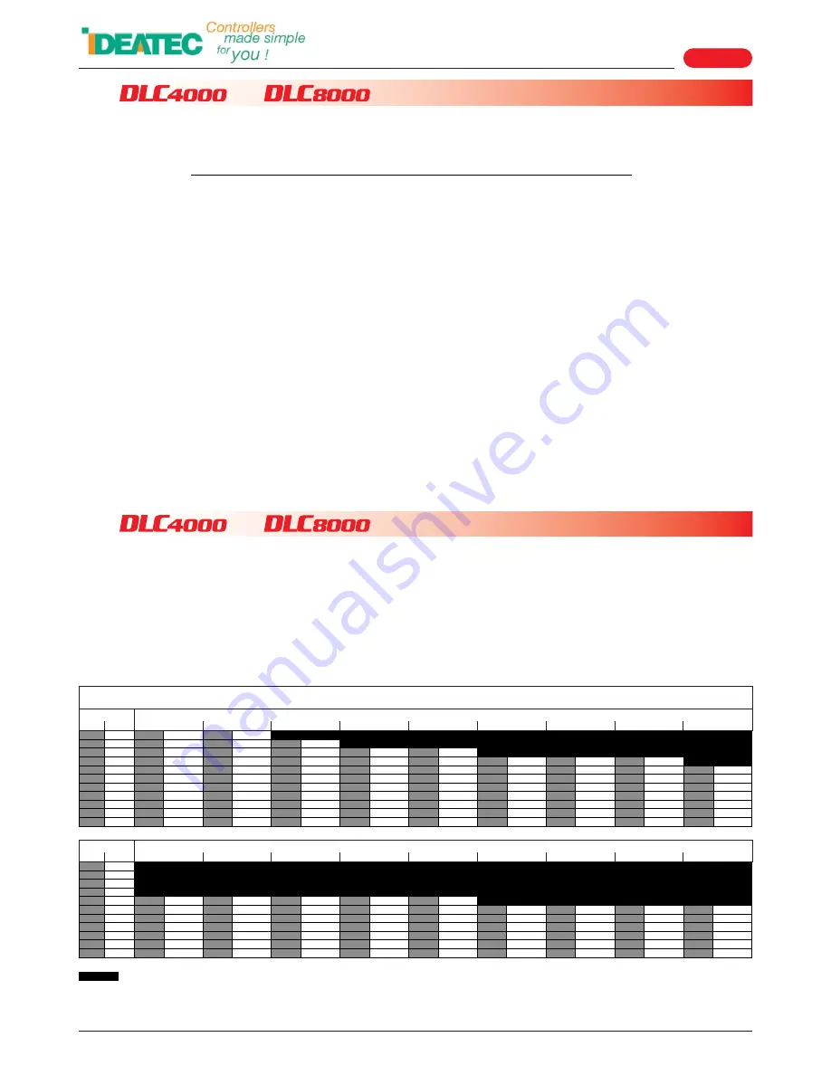
MAXIMUM AUTHORIZED CURRENT

ABACUS FOR THE DIMENSIONING OF ELECTRIC WIRES

Dimensioning of electric wires

Safety and precautions

The safety of future users of this product depends on your installation. Therefore, it is critical that you read, 

understand, and follow all instructions contained in this installation guide.

Some instructions and precautions that must be applied are listed below :

I

To install this equipment correctly, it is essential to have the understanding and the technical skills for the installation 

of automobile electronics.

I

Never install any devices or accessories inside the airbag deployment area. Such installation might reduce the 

effectiveness of the airbag or prevent it from being deployed.  It can also potentially damage or dislodge the device, 
causing serious or fatal injuries.

I

If you need to drill a hole in the dashboard, make sure that both sides are completely free to avoid damaging the 

vehicle.

I

Always install the console or the power module in a ventilated area, and never close to a heat source.

I

It is imperative to dimension correctly all wires installed and connected to the positive battery terminal (see the chart 

on page 2) and protected by a proper fuse placed as close as possible to the battery.

I

To ensure a correct operation of the device installed, it is necessary to make a perfect connection to the negative 

terminal. The negative output of the device must be connected to the negative terminal of the battery as directly as 
possible.

I

The same applies to any elements controlled by the installed device.

I

Make sure that none of the vehicle's original controls are affected by the installed device.

I

Place this installation guide in a safe place and refer to it when necessary and for each installation.

I

Failure to follow safety guidelines and instructions may cause material damages, injuries, or death to you and to 

others.

= Insufficient

It is essential and mandatory to dimension electrical wires correctly according to the currents used and the length of the 
wires. Failure to dimension correctly may cause fire inside the vehicle. 

The DLC4000 & DLC8000 are equipped with protected static output. 

One fuse of max 20A has to be mounted before the DLC4000/DLC8000 as close as possible to the battery.

MAXIMUM AUTHORIZED CURRENT

Summary of Contents for DLC4000

Page 1: ...2 0 81 57 91 70 E mail info ideatec be User s guide DLC4000 DLC8000 Doc V2 1 Firmware V3 1 Page 1 REF P0050F0012 REF P0050F0013 Due to technological advances the manufacturer reserves the right to modify the characteristics of this product without notice USER S GUIDE Control Systems 4 2 or 8 2 outputs 3 inputs ...

Page 2: ...eet 20m 66 Feet 17m 56 5 Feet 15m 49 5 Feet 13 4m 44 Feet 35 2 190m 629 Feet 95m 314 Feet 63m 209 Feet 47m 157 Feet 38m 125 Feet 31m 104 Feet 27m 89 5 Feet 2 9m 78 5 Feet 21m 69 5 Feet FILS mm AWG 5A 10A 15A 20A 25A 30A 35A 40A 45A X MAXIMUM AUTHORIZED CURRENT ABACUS FOR THE DIMENSIONING OF ELECTRIC WIRES Dimensioning of electric wires Safety and precautions The safety of future users of this prod...

Page 3: ... outputs and DLC8000 for 8 positive outputs Both systems also have 2 negative outputs 1 ignition contact positive input 1 negative input 1 positive input A lot of functions are available and configurable through the console From the functions available interlock function blue light siren interlock function blue light grill light marking functions linked or not to handbrake siren status and or blue...

Page 4: ... 9 screw terminals 4 3 Power module 4 Elements identification continued 4 2 Bus cable 2xRJ45 Console Module In order to ensure perfect operation only BUS cables assembled and supplied by the manufacturer are accepted Otherwise unless authorised in writing the manufacturer will not accept any warranty or liability on the equipment installed Standard length 5 meters P N P0020F0027 FTP Option sur dem...

Page 5: ...screws Ü Choose the best place to install the console on the dashboard Ü Locate and note the 6 fixation holes at the base of the foot Ü Fix the base and position of the console perfectly Ü Block the 2 hexagonal head screws Ü Attach the cover to the back of the foot with the screw provided Ü Place the small black cap on the head of the screw on the back ÜIf the angle chosen to install the console a...

Page 6: ...the power module in a ventilated area and never close to a heat source ÜTake into account the size of the different connectors that will be added to the assembly The power module must be protected against humidity Do not attempt to enlarge the mounting holes The safety of future users of this product depends on your installation Therefore it is critical that you read understand and follow all inst...

Page 7: ... CM Page 7 50 00 mm 4 00 mm CHECK THE SCALE X Y AFTER PRINTING ATTENTION THE DRILLING TEMPLATES WERE CREATED BY THE EDITOR USING A 1 1 SCALE FOR THIS REASON SOME PRINTERS OR PRINTING SOFTWARE MAY CAUSE DISTORTIONS ON PRINTING YOU SHOULD VERIFY THE SCALE BEFORE USING THE TEMPLATES BELOW 6 1 Controlling the Template Scale after Printing The rulers below allow you to control the scale on the two axes...

Page 8: ...ernelmont Belgium Tel 32 0 81 42 00 10 Fax 32 0 81 57 91 70 E mail info ideatec be User s guide DLC4000 DLC8000 Doc V2 1 Firmware V3 1 Page 8 82 mm 72 8 mm 67 mm 94 mm 6 6 6 3 DLC4000 DLC8000 power module Drilling Templates continued CHECK THE SCALE X Y AFTER PRINTING ...

Page 9: ...n Obligatory Fuse max 20A DLC4000 Console DLC8000 DLC4000 Module DLC8000 Technical characteristics 7 1 Console 7 2 Power module Operating Voltage Operating Temperature Connection Type Weight Dimensions L x W x D Automatic Backlighting Multidirectional Foot Mounting 5VDC 5 supplied by the module de 25 C à 60 C RJ45 non crossed 115 gr 95 x 70 x 35 mm without the foot Operating Voltage Operating Temp...

Page 10: ...xion originally supplied 9 1 Connectors and Wire Terminals Supplied To ensure correct and reliable connections it is imperative to crimp an adequate terminal on each wire Obligatory Fuse max 20A POWER SUPPLY 10 28 VDC To DLC8000 console Ignition positive input 1 Negative input 2 OUTPUT 1 OUTPUT 3 OUTPUT 4 Obligatory Fuse max 20A Power supply 10 28 VDC To DLC4000 console Ignition positive input 1 N...

Page 11: ...tivated and not activated again when handbrake is released Siren can be activated by positive input 3 switch mode when input 3 signal disappears then siren is going OFF too B3 POSITIVE OUTPUT 3 Function for B3 linked to key B1 If user pushes on the key B1 then the key B3 is activated too Automatically disabled when handbrake is activated and not activated again when handbrake is released B4 POSITI...

Page 12: ...the console backlighting will be activated Key B4 will stop sending its brief light signal If some outputs are configured in permanent mode no function on the linked key then they are automatically activated 11 3 2 The key B1 B2 B3 or B4 is permanently lit This state indicates that the function associated with that key is activated therefore simply press the key again to turn it off and desactivat...

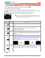
Page 13: ...C8000 Mode 1 allows you to configure the keys 1 to keys 8 and inputs Mode 2 allows you to configure conditions and simulation for arrow stick functions and standby modes Connect power module on power supply and keep keys B1 and B3 for mode 1 pressed Fig 1 or keys B2 and B4 pressed for mode 2 Fig 2 until the console emits a repetitive beep then release them You are in configuration mode then you ha...

Page 14: ... 4 4 To save your configuration When you finish your selection save your configuration by pressing B1 B3 if you were in the mode 1 B2 B4 if you were in mode 2 once again during 3 seconds CONSOLE DLC4000 Example 1 CONSOLE DLC8000 Example 2 11 4 3 To enter in configuration mode continued When you enter into configuration mode each key is flashing several times cyclically The number of flashes is cor...

Page 15: ...put Key B1 is by default the Master key for all the functions linked in the B2 B2 or B4 configurations The positive input 3 functions are also configured by B1 key in configuration mode 1 one pulse on the key SELECTION FLASHES DESCRIPTION Key B1 is available and activates the positive output 1 Key B1 is the Master key by default Positive input 3 is an input for blue light status if key B2 is confi...

Page 16: ... is configured in siren mode The siren is working until the signal on input 3 is active siren can always be activated or disabled by the key B2 Key B1 is a switch and activates the positive output 1 Key B1 is the Master key by default Positive input 3 is a external activator in switch mode if the key B2 is configured in siren mode and the key B1 blue light is already activated The siren is working...

Page 17: ...negative output 1 Key B2 working is conditioned by the negative input2 handbrake signal If the signal is present on negative input 2 the key B2 is disabled and cannot be activated until the signal is still present Key B2 is not automatically activated if the signal on negative input 2 disapears Key B2 is a switch in Slave mode and activates the positive output 2 negative output 1 Key B2 working is...

Page 18: ...t 2 siren status When the siren is activated she send back a negative signal to confirm that all is working perfectly If this signal disappears then after 4 seconds key B2 is going OFF automatically Siren can be started again but only by pressing key B2 Key B2 is a switch controlling positive output 2 negative output 1 and is conditioned by the key B1 Master key blue light Key B2 working is condit...

Page 19: ...ve output going OFF only when console is off or the power supply of the DLC4000 or DLC8000 is disconnected iIn order to avoid configuration mistakes it is impossible to configure key B3 in grill light mode if the key B1 is disabled It is also impossible to disable Key B1 if the key B3 is already configured in grill light mode Key B3 is a switch in grill light mode and controls the positive output ...

Page 20: ...can be used as markup function Some functions are linked to the negative input 2 Key B4 is a momentary push button and activates the positive output 4 negative output 2 when it is pressed and the 2 ouputs are going OFF when key B4 is released Key B4 is a switch and activates the positive output 4 negative output 2 No condition Key B4 is not available and the positive output 4 negative output 2 are...

Page 21: ... without handbrake condition Some functions are linked to the negative input 2 Key B5 is a switch and is included in the group 1 with B6 B7 and B8 if they are configured in group 1 mode See the description of the function group 1 on page 25 Special conditions with negative input 2 for group 1 are available in configuration mode 2 see page 28 Key B5 is a switch and is included in the group 2 with B...

Page 22: ...nked to the negative input 2 Key B6 is a switch and is included in the group 1 with B5 B7 and B8 if they are configured in group 1 mode See the description of the function group 1 on page 25 Special conditions with negative input 2 for group 1 are available in configuration mode 2 see page 28 Key B6 is a switch and is included in the group 2 with B5 B7 and B8 if they are configured in group 2 mode...

Page 23: ...of the DLC8000 is disconnected Key B7 can be used as arrowstick controller with or without handbrake condition Some functions are linked to the negative input 2 Key B7 is a switch and is included in the group 1 with B5 B6 and B8 if they are configured in group 1 mode See the description of the function group 1 on page 25 Special conditions with negative input 2 for group 1 are available in configu...

Page 24: ...of the DLC8000 is disconnected Key B7 can be used as arrowstick controller with or without handbrake condition Some functions are linked to the negative input 2 Key B8 is a switch and is included in the group 1 with B5 B6 and B7 if they are configured in group 1 mode See the description of the function group 1 on page 25 Special conditions with negative input 2 for group 1 are available in configu...

Page 25: ...R K5 2A max 2A max IN 3 POWER SUPPLY 10 30 VDC IN 1 IN 2 www ideatec be e6 03 0331 CE K2 Positive outlets 10A max Read user s guide before use K1 K3 K4 BUS BUS TO CONSOLE q K2 K6 K4 K7 K7 K8 K8 POWER K5 2A max 2A max IN 3 POWER SUPPLY 10 30 VDC IN 1 IN 2 www ideatec be e6 03 0331 CE K2 Positive outlets 10A max Read user s guide before use K1 K3 K4 BUS BUS TO CONSOLE q K2 K6 K4 K7 K7 K8 K8 POWER K5...

Page 26: ... B1 B5 B6 B3 B7 B8 B2 B4 B1 i Operation Configuration continued 11 5 DLC8000 Configuration MODE 1 continued Some options for keys B1 B2 B3 and B4 are not compatible with scenes configured on B5 and B6 example momentary push button for the key B1 11 5 11 Description of the scenes 1 and 2 controlled by B5 and B6 keys DLC8000 only Keys B5 and B6 can be configured like scene 1 and scene 2 activators s...

Page 27: ...nt on positive input 1 of the DLC4000 DLC8000 Automatic standby after 15 minutes if no keys are activated and positive signal from ingnition is not present on positive input 1 of the DLC4000 DLC8000 If long press on key B4 then all the keys are going OFF permanent outputs stay ON and the system is falling into sleep after 20 seconds permanent outputs are going OFF Automatic standby after 1 minute ...

Page 28: ... directional lightbar configuration DLC8000 only The configuration is made by the key B5 and gives the possibility to configure conditions with negative input 2 handbrake for the keys B5 B6 B7 and B8 if they are configured in group 1 or group 2 mode Keys B5 B6 B7 and B8 are conditioned by negative input 2 handbrake if they are configured in group 1 or group 2 mode and the negative input 2 combined...

Page 29: ... B7 B8 B2 B4 B1 B5 B6 B3 B7 B8 B2 B4 B1 B5 B6 B3 B7 B8 B2 B4 B1 B5 B6 B3 B7 B8 B2 B4 B1 Operation Configuration continued 11 6 DLC4000 DLC8000 Configuration MODE 2 continued Simulation for directional lightbar is available No directional lightbar simulation If B5 is ON If B7 is ON If B8 is ON 11 6 4 Simulation for the directional lightbar DLC8000 only Configuration on the key B6 The simulation for...

Page 30: ... is known and manufactured 3 This warranty does not apply if the model or serial number on the product has been altered erased suppressed or illegible 4 This warranty does not cover any of the following points a Periodic maintenance and repair or replacement of parts from normal usage b Any adaptations or modifications aimed at improving the product such as it has been purchased and described in t...

Page 31: ...tion 3 2 View of assembly Chapter 4 Elements identification 4 1 Console 4 2 Bus cable 2xRJ45 Console Module 4 3 Power module 4 4 Pictogram collection Chapter 5 Console and Module installation 5 1 Console 5 2 Power module Chapter 6 Drilling Templates 6 1 Controlling the template scale after printing 6 2 Console mounting foot 6 3 DLC4000 DLC8000 Power module Chapter 7 Technical characteristics 7 1 C...

Page 32: ... save your configuration 11 5 DLC4000 DLC8000 Configuration Mode 1 11 5 1 Key B1 and positive input 3 configuration 11 5 2 Key B2 and negative input 2 configuration 11 5 3 Key B3 and negative input 2configuration 11 5 4 Key B4 and negative input 2configuration 11 5 5 Key B5 configuration DLC8000 only 11 5 6 Key B6 configuration DLC8000 only 11 5 7 Key B7 configuration DLC8000 only 11 5 8 Key B8 co...

Reviews: