B-1908-1(0)
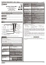
INSTRUCTION SHEET - HS1L Series
Solenoid Type Safety Switch, Inside Connector type
( 1 / 6 )
2016.08
2
Specifications and Ratings
CAUTION
Solenoid lock type
• This safety switch is designed to lock the actuator while the solenoid is energized
and to release it when deenergized.
• When the power to the solenoid is interrupted by accident, such as disconnection,
the lock is released before a machine stops ompletely. Then, the worker may be
exposed to hazards.
• This safety switch can be used only for limited applications which do not
especially need to be locked for safety.
1
Type
Circuit Code
DQ : 1NC + 1NC 1NO
1NO
1NC + 1NC
DT : 1NC + 1NC 1NC
1NC
1NC + 1NC
Main
circuit
Door monitor
circuit
Lock monitor
circuit
EN ISO / ISO14119, GB14048.5
IEC60947-5-1, EN60947-5-1
GS-ET-19, UL508, CSA C22.2 No.14
IEC60204-1/EN60204-1
-20 to +55°C (no freezing)
2.5A
Applicable Standards
Standards for Use
Machinery Directive, Low Voltage Direc ive
Applicable Directives
Operating
Condition
Thermal Current ‹Ith›
Contact Ratings
( Reference Values )
‹Ue, Ie›
Operating Temperature
45 to 85%RH (no condensation)
Operating Humidity
3
Pollution Degree
30V 125V 250V
Class of Protection
-40 to +80°C (no freezing)
Storage Temperature
Resistive load (AC-12)
Inductive load (AC-15)
Resistive load (DC-12)
Inductive load (DC-13)
DC
2.5A 2.5A 2.5A
AC
2.5A 2.5A 2.5A
2.5A 2.2A 1.1A
2.5A 1.1A 0.6A
Class
II
(IEC61140) *1
GB14048.5
2,000m maximum
Altitude
2 5kV
(Between ground and LED, solenoid circuit : 1.5kV)
Impulse withstand voltage ‹Uimp›
250V
(Between ground and LED, solenoid circuit : 30V)
Rated insulation voltage ‹Ui›
Interlocking device Type
/ the level of coded
Type 2 Interlocking device
/ low level coded actuator (EN ISO / ISO14119)
0.05 to 1.0 m/s
11mm min.
50N min.
300mΩmax. (Initial value) *5
250V, 10A fast acting type fuse *6
24VDC 100%ED
200mA (Initial value)
Rated Voltage × 85% max. (at 20
°C
)
Rated Voltage × 10% min. (at 20
°C
)
Approx. 5W
24VDC
10mA
LED
R(Red), G(Green) (Φ12 Lens)
Approx. 450g
900 operations/hour
Operating Frequency
Operating Speed
Actuator Tensile Strength
when Locked
Direct Opening Travel
Direct Opening Force
Contact Resistance
Short-circuit protective device
Rated Operating Voltage
Rated Current
Turn ON Voltage
Turn OFF Voltage
Rated Power Consumption
Rated Operating Voltage
Rated Current
Light Source
Lens Color
Weight
Damage Limits
1,000m/s
2
Operating Extremes 10 to 55 Hz, half amplitude 0 35 mm
Damage Limits
30 Hz, half amplitude 1.5 mm
Electrical Durability
1,000,000 operations min. (GS-ET-19)
Ind c v loa (
1 1A 0 6A
2,000,000 (EN ISO 13849-1 Annex C Table C.1)
B10d
Mechanical Durability
100,000 operations min.
(900 operations / hour, Rated Load)
(900 operations / hour, 24V AC/DC 0.1A Resistive Load)
1,000,000 operations min.
IP67 (IEC60529)
Degree of Protection
100A (250V)
Conditional short circuit current
Solenoid
Indicator
Shock Resistance
Vibration Resistance
Fzh=3,000N minimum
F1max.=3,900N minimum (GS-ET-19) *2, *3, *4
Ratings approved by safety agencies
(1) TÜV rating
AC-15 250V, 2.5A
DC-13 30V, 2.5A
(2) UL , c-UL rating
2.5A, 250V ac, General Use
2.5A, 250V ac, Resistive
2.5A, 30V dc
(3) CCC rating
AC-15 2.5A, 250V ac
DC-13 2.5A, 30V dc
*1 Basic insulation of 2.5kV impulse withstand voltage is ensured between different
contact circuits and between contact circuits and LED or solenoid in the enclosure.
When both SELV (safety extra low voltage) or PELV (protective extra low voltage)
circuits and other circuits (such as 230V AC circuits) are used for the solenoid
power and contact circuits at the same time, the SELV or PELV requirements are
not met any more.
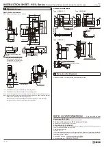
*2 See item 8 Dimensions.
*3 The actuator locking strength is rated at 3,000N of sta ic load. Do not apply a load
higher than the rated value. When a higher load is expected to work on the
actuator, provide an additional system consisting of another safety switch without
lock (such as the HS5D safety switch) or a sensor to detect door opening and stop
the machine.
*4 F1max. is maximum force. The actuator’s guard-locking force Fzh is calculated in
accodance with GS-ET-19:
*5 When applicable connector and 1m cable (0.3mm
2
AWG22) are connected.
*6 Make sure that a fast acting fuse for short-circuit protection trips before overheating
of the wires.
Fzh
=
maximum force (F1max )
Safety coefficient (=1.3)
Thank you for purchasing this IDEC product. Confirm that the delivered product is
what you have ordered. Read this instruction sheet to make sure of correct operation.
In this operation instruction sheet, safety precautions are categorized in order of
importance to Warning and Caution :
Warning notices are used to emphasize that improper operation may cause severe
personal injury or death.
Caution notices are used where inattention might cause personal injury or damage to
equipment.
INSTRUCTION SHEET
Original Instructions
Solenoid Type Safety Switch
HS1L Series
Inside Connector type
S A F E T Y P R E C A U T I O N S
CAUTION
WARNING
Solenoid voltage / Lock Mechanism
4 : 24V DC / Spring Lock
7Y : 24V DC / Solenoid Lock
Indicator voltage
4 : 24V DC
[0] : Without Indicator
Conduit Type
blank :
G1/2
P : PG13.5
M : M20
Body Color
R : Red/Black
Indicator Color
G : Green
R : Red
HS1L-DQ44KMSRPC-G
Actuator Tensile Strength
when Locked
MS : 3,000N
Manual unlock key
[blank] : Without Manual Unlock Key
K : With Manual Unlock Key
Type Nos. in [ ] are not supplied as standard.
Contact IDEC if required.
Wiring method
C : With Connector


