background image

( 8 / 9 )

B-2048-1(1)

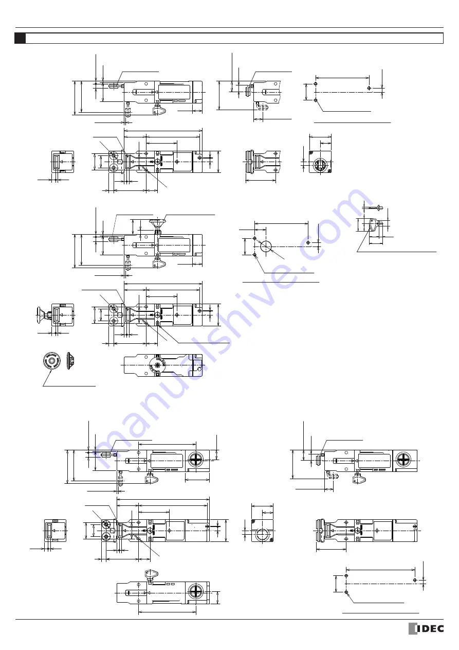
INSTRUCTION SHEET - HS1T Series 

Solenoid Type Safety Switch

2019.07

Dimensions (mm)

3-M5 Safety Switch 

Mounting Holes

Type

 : HS1T-

4ZSM

Type

 : HS1T-

4ZM

Type

 : HS1T-

4ZLM                

For L-type actuators

8

Safety Switch dimensions

φ

10

(

24

)

6 5

24 5

)

18

3

15

9

Slot Plug

30

40

20

7

45

22

54.9

52.3

(

19.1

±

0.5

)

11.5

(

16.6

±

0.5

)

22.5

104.6

17.5

104.6

4

7.1

40

7

1

170

125.5

40.1

56.2

59.4

9

20.8

30

φ

5.2

4.6

4

61.6

2.5

(

5.1

±

0.5

)

35

(

2.6

±

0.5

)

56.8

(

8

)

Slot Plug

14


7

8

30

97.8

φ

20

20.8

30

40

143

97.8

40.1

56 2

7

1

59.4

9

20.8

30

φ

5.2

61.6

2

5

(

5.1

±

0.5

)

17.8

35

(

2.6

±

0.5

)

56.8

4

7.1

(

8

)

4.6

4

22

φ

5.1

7.7

27

Rear Unlock Indicator

Rear Unlock Button

Rear Unlock Button

(RP)

(RP)

7~8

30

125.5

Main body moun ing hole layout

HS9Z-A12T

Actuator

HS9Z-A11T

Actuator

Slot Plug 

(

取付基準

)

Actuator center position

30

40

143

97.8

40.1

56 2

59.4

9

20.8

30

40

20

6.5

61.6

2.5

17.8

35

56.8

4

7.1

22

54.9

52.3

(

19.1

±

0.5

)

11

5

(

16.6

±

0.5

)

7

1

(

5.1

±

0.5

)

(

2.6

±

0.5

)

(

8

)

4.6

4

φ

5.2

φ

5.1

φ

5.1

7

8

30

97.8

HS9Z-A11T

Actuator

HS9Z-A12T

Actuator

HS9Z-A11T

Actuator

Main body mounting hole layout

Manual Unlock Key (Supplied)

Main body mounting hole layout

3-M5 Safety Switch 

Mounting Holes

(For straight actuators )

3-M5 Safety Switch 

Mounting Holes

(RP)

(RP)

(RP)

(RP)

(RP)

(RP)

(RP)

*14


When not in use, close up  he safety switch actuator entry slots with slot plugs

 to prevent dust from entering.

 (Actuator entry slots on the front come closed up with slot plugs at time of shipment.)

Summary of Contents for HS1T Series

Page 1: ...cle 10 mA LED Green Type 2 Interlocking device low level coded actuator EN ISO ISO14119 EN ISO ISO14119 IEC60947 5 1 EN60947 5 1 GS ET 19 UL508 CSA C22 2 No 14 GB T 14048 5 IEC60204 1 EN60204 1 Low Voltage Directive Machinery Directive 2 5A AC Resistive load AC12 Inductive load AC15 DC Resistive load DC12 Inductive load DC13 30V 125V 250V 2 5A 1 5A 1 5A 0 75A 2 0A 0 4A 0 2A 1 0A 0 22A 0 1A Class I...

Page 2: ...ctual applica ion before installation Actuator Mounting Reference Position As shown below the mounting reference position of the actuator inserted into the safety switch is After mounting the actuator remove the actuator stop from the safety switch When using the safety switch for a hinged door the minimum radius of the applicable door is shown in the following figures Minimum Radius of Hinged Doo...

Page 3: ... cycling testing of the device to the control system to prevent product failure Regardless of door types do not use the safety switch as a door stop Install a mechanical door stop to the end of the door to protect the safety switch against excessive force Mount the actuator so that it will not hit the operator when the door is open other wise injury may be caused Pay attention to the management of...

Page 4: ... safety hedge Use the rear unlock indicator by attaching it to the display area on either side of the safety switch The Rear Unlock Button Lock Release Rear Unlock Status Normal Status Contact Configuration and Operation Contact Congifiguration 11 9 HS1T TJ HS1T TG HS1T TF HS1T TD HS1T TC HS1T TB HS1T TA HS1T J HS1T G HS1T F HS1T D HS1T C HS1T B HS1T A HS1T XB HS1T DD HS1T VG HS1T VH HS1T VF HS1T ...

Page 5: ...ng for guard locking devices Section 5 7 2 2 When a lock monitor circuit contact has the locking monitoring marking it means that one circuit contact can monitor the position and the locking function of the protective door The locking monitoring circuit contact turns ON only when the protective door is closed and locked note Both types of HS1T safety switches spring lock type switches and solenoid...

Page 6: ...of gasket is completely tightening the cable The waterproof gasket is not properly tightening the cable Spring Force Terminal Spring Force Terminal Safety Switch A Gasket Sheath B Terminal Cover CAUTION Make sure not to lose any screw when removing the terminal cover from the switch Please make sure the cable is insterted deep enough into the terminal cover so that the waterproof gasket can tighte...

Page 7: ...d by IDEC CORPORATION HS9Z A11T Actuator HS1T VB4 Safety Switch with Solenoid Used as open close monitor of guard Guard Open Output Circuit HR1S AF Safety relay module One of the example of the circuit Safety relay module HR1S AF series manufactured by IDEC CORPORATION HS9Z A11T Actuator HS1T VB4 Safety Switch with Solenoid Used as open close monitor of guard Guard Open Example of a circuit diagra...

Page 8: ...ator Rear Unlock Button Rear Unlock Button RP RP 7 8 30 125 5 Main body moun ing hole layout HS9Z A12T Actuator HS9Z A11T Actuator Slot Plug 取付基準 Actuator center position 30 40 143 97 8 40 1 56 2 59 4 9 20 8 30 40 20 6 5 61 6 2 5 17 8 35 56 8 4 7 1 22 54 9 52 3 19 1 0 5 11 5 16 6 0 5 7 1 5 1 0 5 2 6 0 5 8 4 6 4 φ 5 2 φ 5 1 φ 5 1 7 8 30 97 8 HS9Z A11T Actuator HS9Z A12T Actuator HS9Z A11T Actuator ...

Page 9: ... its validity Applicable EU Directive Low Voltage Directive 2014 35 EU Machinery Directive 2006 42 EC RoHS Directive 2011 65 EU Applicable Standard s EN 60947 5 1 GS ET 19 EN 50581 20 5 11 5 22 40 40 42 5 12 3 0 8 43 18 6 3 5 1 φ 5 1 φ 15 90 22 40 22 43 18 6 47 9 19 3 0 8 φ 5 1 φ 15 When installed on 3 5 1 Actuator Stop Supplied with actuator When installed on Actuator dimensions Type HS9Z A11T To...

Reviews: