background image

69

HS5E-K Interlock Switches with Key

Instructions

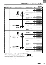
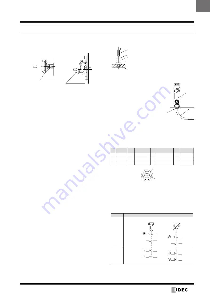
 Manual Unlocking using the Rear Unlock-

ing Button


The rear unlocking button is used by the operator confined 

in a hazardous area for emergency escape .

Unlock

Rear Unlocking Button

Unlock

Rear Unlocking

Button Kit

How to operate


When the rear unlocking button is pressed, the interlock 

switch is unlocked and the door can be opened .


To lock the interlock switch, pull back the button .


When the button remains pressed, the interlock switch 

cannot be locked even if the door is closed, and the main 

circuit remains open .

Safety Precautions


Install the rear unlocking button in a place where only the 

operator inside the hazardous area can use it . Do not 

install the button in a place where an operator outside the 

hazardous area can use it, otherwise the interlock switch 

may be unlocked during usual machine operation, causing 

danger .


Operate the rear unlocking button by hand only . Do not 

operate using  a tool or with excessive force . Do not apply 

force to the button from the direction other than the proper 

direction, otherwise the button will be damaged .

Recommended Tightening Torque for 

Mounting Screws


HS5E-K interlock switch: 1 .8 to 2 .2 N·m (four M4 screws) 

(Note) 


Rear unlocking button: 0 .5 to 0 .7 N·m


Rear unlocking button kit: 4 .8 to 5 .2 N·m (M5 Screw)


Actuators 

HS9Z-A51: 

1 .8 to 2 .2 N·m (two M4 screws) (Note)  

HS9Z-A52:  

0 .8 to 1 .2 N·m (two M4 Phillips screws) 

HS9Z-A51A/A52A: 1 .0 to 1 .5 N·m (two M4 screws) (Note) 

HS9Z-A53: 

4 .5 to 5 .5 N·m (two M6 screws) (Note)

HS9Z-A55: 

1 .0 to 1 .5 N·m (two M4 screws) (Note)

Note:  The above recommended tightening torques of the 

mounting screws are the values confirmed with hex socket 

head bolts . When other screws are used and tightened to a 

smaller torque, make sure that the screws do not become 

loose after mounting .


Mounting bolts must be provided by the users .


To avoid unauthorized or unintended removal of the in-

terlock switch and the actuator, it is recommended that 

the interlock switch and actuator are installed in a secure 

manner, for example using special screws or welding the 

screws .


When installing the HS9Z-A51A and HS9Z-A52A actua-

tors, use the washer (supplied with the actuator) on the 

hinged door, and mount tightly using two M4 screws .

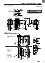
M4 Screw Hole

Hinged Door

Note: Choose mounting centers of
either 12 mm or 20 mm.

M4 Screw

Rubber Bushing

Washer


Cables


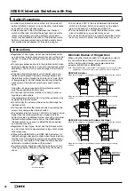
Do not fasten or loosen the gland at 

the bottom of the interlock switch .


When bending the cable during wir-

ing, make sure that the cable radius 

is kept at 30 mm minimum .


When wiring, make sure that water 

or oil does not enter the cable .


Do not open the lid of the interlock 

switch . Otherwise the interlock 

switch will be damaged .

Wire Identification


Wires can be identified by color and white line printed on 

the wire .


Wires whose colors are white, black, gray and gray/white 

cannot be used .

No . Insulation No .

Insulation

No .

Insulation

No .

Insulation

1 White

4

Blue

7 Blue/White

10 Pink/White

2 Black

5

Brown/White

8 Orange/White

11 Gray

3 Brown

6

Orange

9 Pink

12 Gray/White

Jacket

Insulation

2

1

10

12

9 11

8

7

6

4

3

5

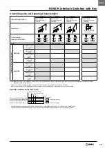
Circuit Code Identification


Circuit codes can be identified by the insulation color in 

each contact configuration .


The following table shows the identification of circuit 

numbers .


When wiring, cut unnecessary wires such as the dummy 

insulation (white) and any unused wires .

Door Monitor

HS5E-KVA

HS5E-KVD

11

12

42

41

52

51

53

54

41

42

12

23

11

24

Contact Configuration

Model

LOCK

UNLOCK

22

21

Monitor Circuit: Blue

Monitor Circuit: Orange
Monitor Circuit:

Monitor Circuit:

Monitor Circuit: Blue

Monitor Circuit: Orange
Monitor Circuit:

Monitor Circuit:

Orange/White

Brown

Pink

Brown

Pink

Blue/White

Orange/White

Blue/White

Pink/White

Brown/White

Pink/White

Brown/White

• The contact configuration shows the status where the actuator is 

inserted and the switch is locked .

30 mm

Gland

Minimum

Radius

Lid

(48)

HS5E-K

Summary of Contents for HS5E-K

Page 1: ...C megger Between terminals of the same pole 100 MΩ minimum Electric Shock Class Class II IEC61140 Degree of Protection IP65 IEC60529 Shock Resistance Operating extremes 100 m s2 Damage limits 1 000 m s2 Vibration Resistance Operating extremes 10 to 55 Hz amplitude 0 35 mm Damage limits 30 Hz amplitude 1 5 mm Actuator Operating Speed 0 05 to 1 0 m s Direct Opening Travel Actuator HS9Z A51 11 mm min...

Page 2: ...tection circuitry is employed in the HS5E K With this innovative function the monitor circuit 41 42 turns off when the head is removed from the switch such as when removing the head to change the head direction applicable with all models of HS5E K With the head installed on the switch monitor circuits 41 42 and 51 52 operate in synchronization while the key locks unlocks the actuator When the head...

Page 3: ... Monitor Circuit Monitor Circuit Monitor Circuit Monitor Circuit Monitor Circuit Monitor Circuit Monitor Circuit Monitor Circuit A removable in all positions 3m HS5E KVA0L03 2A 5m HS5E KVA0L05 2A B removal in UNLOCK position 3m HS5E KVA0L03 2B 5m HS5E KVA0L05 2B C removable in LOCK position 3m HS5E KVA0L03 2C 5m HS5E KVA0L05 2C VD A removable in all positions 3m HS5E KVD0L03 2A 5m HS5E KVD0L05 2A ...

Page 4: ...al Mounting Straight Actuator HS9Z A51 Plug the unused actuator entry slot using the plug supplied with the switch Actuator Mounting Reference Position As shown in the figure on the right the mounting reference position of the actuator when inserted in the interlock switch is the position where the actuator stop placed on the actuator lightly touches the side surface of the interlock switch Note A...

Page 5: ... Unit for left hand door HS9Z DH5LH Switch Cover Unit HS9Z DH5C Used for installing the interlock switch inside Plug Actuator HS9Z A5P Padlock Hasp HS9Z PH5 Mounting Plate Note 1 HS9Z SP51 Can be used for mounting on aluminum frames Rear Unlocking Button Kit HS9Z FL53 Used when the total thickness of mounting frame panel and mounting plate is 23 X 33 20 X 30 when switch cover unit HS9Z DH5C is use...

Page 6: ...2 mm the actuator has flexibility both vertically and horizontally When the mounting center distance is set to 20 mm the actuator swings vertically Adjust the distance by moving the rubber bushings Note The actuator stop film and actuator stop are supplied with the actuator and used when adjusting the actuator position Remove after the actuator position is determined Angle Adjustable Actuator Vert...

Page 7: ... 13 to 20 6 to 16 36 to 46 8 to 20 7 to 9 Rear Unlocking Button Hole ø22 to 30 Note 1 Rear Unlocking Button Hole ø22 to 30 Note 1 7 to 9 8 to 20 36 to 46 6 to 16 13 to 20 Door Gap Door Gap Door Gap Door Gap 7 to 9 256 204 102 49 5 35 47 5 26 47 5 7 to 9 mm 102 26 40 40 40 40 49 5 UNLOCK LOCK 4 6 M5 4 6 M5 2 M5 6 M5 Reference Reference 3 mm 2 mm 4 mm Mounting Position Tolerance 0 8 mm Front View Re...

Page 8: ...9Z PH5 60 28 16 5 2 R4 8 2 ø8 Mounting Plate HS9Z SP51 4 R6 4 2 12 8 2 6 6 4 R 3 3 4 M4 6 10 40 170 21 106 187 50 7 42 2 22 4 C 3 40 21 ø 1 8 R e a r U n l o c k i n g B u t t o n H o l e 64 1 13 4 187 Drilling Rear Unlocking Button Hole 4 M4 Screw 4 M4 Screw When installing the HS5E K L rear unlocking button provide a rear unlocking button a hole on the HS9Z SP51 N o t e 106 20 to 22 13 4 ø18 Rea...

Page 9: ... Circuit door closed 21 22 Monitor Circuit locked 41 42 Monitor Circuit locked 51 52 Note When the operator is confined in a hazardous area the actuator can be unlocked manually by pressing the rear unlocking button which should be accessed easily by the operator The above contact configuration shows the status when the actuator is inserted and the switch is locked Monitor circuit Sends monitoring...

Page 10: ...tor retention force is 1 400N Do not apply a load higher than the rated value When a higher load is ex pected provide an additional system consisting of another interlock switch without lock such as the HS5D HS5B interlock switch or a sensor to detect the door opening and stop the machine Regardless of door types do not use the interlock switch as a door lock Install a separate lock using a latch ...

Page 11: ...Doors HS5E K Interlock Switch Install the interlock switch on the immovable part of the door Install the actuator on the movable part of the door HS9Z A52 Actuator HS9Z SH5 Sliding Actuator Door Installing the Head Do not use plastic and metallic heads of HS5D HS5B interlock switches on the HS5E K Be sure to use HS5E metallic heads The metal heads of the HS5E HS5D and HS5B look similar When using ...

Page 12: ...lling the rear unlocking button apply Loctite to the screw so that the screw dose not become loose The button is made of glass reinforced PA66 66 nylon The screw is made of iron Take the compatibility of the plastic material and Loctite into consideration Mounting the Rear Unlocking Button Kit 1 Install a connecting rod onto the push rod on the HS5E K rear unlocking button interlock switch HS5E K ...

Page 13: ...rs To avoid unauthorized or unintended removal of the in terlock switch and the actuator it is recommended that the interlock switch and actuator are installed in a secure manner for example using special screws or welding the screws When installing the HS9Z A51A and HS9Z A52A actua tors use the washer supplied with the actuator on the hinged door and mount tightly using two M4 screws M4 Screw Hol...

Page 14: ...afety Input 2 T2 X2 T3 X3 Safety Input 6 T12 X12 T13 X13 Safety Input 5 T10 X10 T11 X11 Safety Input 4 T6 X6 T7 X7 Safety Input 3 T4 X4 T5 X5 Start Input 1 X16 Start Input 2 X17 External Device Monitor 1 T14 X14 Monitor Input Monitor Input External Device Monitor Self hold function circuit 1 Mode Select II Hold Trigger Self hold function Self hold function circuit 2 Y0 Y1 Y2 Y3 Safety Output 1 Saf...

Page 15: ...roller Select force guided relays for K3 K4 K5 and K6 according to the operation control circuits of the robots Teach Mode Auto Mode Y0 Y1 EDM Self hold function circuit 2 Self hold function circuit 1 OSSD OSSD FS1A C11S LOGIC 13b inside the guard Control FS1A C11S LOGIC103 Teach Mode Auto Mode Y0 Y1 EDM Self hold function circuit 2 Self hold function circuit 3 Self hold function circuit 1 FS1A C1...

Reviews: