background image

FC6A S

ERIES

 MICROS

MART

 L

ADDER

 P

ROGRAMMING

 M

ANUAL

 FC9Y-B1726

11-1

11: W

EEK

 P

ROGRAMMER

 I

NSTRUCTIONS

This chapter describes the week programmer instructions that are used to turn outputs on and off on the specified days of the 
week or dates and times.

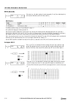
WKTIM (Week Timer)

Compares the specified day of the week, start time, and end time with the current time and outputs that result.

Note: 

The WKTIM instruction is compatible with the FC5A Series MICROSmart WKTIM instruction. For details on the WKTIM instruction, see 

Chapter 9 "WKTIM (Week Timer)" in the "FC5A Series MICROSmart Pentra User's Manual Advanced Volume".

WKTBL (Week Table)

Sets the specified month and day as a special date.

Note: 

The WKTBL instruction is compatible with the FC5A Series MICROSmart WKTBL instruction. For details on the WKTBL instruction, see 

Chapter 9 "WKTBL (Week Table)" in the "FC5A Series MICROSmart Pentra User's Manual Advanced Volume".

WEEK (Weekly Timer)

Compares the specified day of the week, ON time, and OFF time with the current time and outputs that result.

Note: 

For details on the WEEK instruction, see "WEEK (Weekly Timer)" on page 11-3.

YEAR (Yearly Timer)

Compares the specified date with the current date and outputs that result. This allows the special dates within a one-year period 
to be specified.

Note: 

For details on the YEAR instruction, see "YEAR (Yearly Timer)" on page 11-16.

D1

*****

S2

*****

WKTIM

S1

*****

S3

*****

Sn

*****

S1

*****

WKTBL

・・・

・・・

D1

*****

S2

*****

WEEK

S1

*****

S3

*****

D1

*****

S2

*****

YEAR

S1

*****

S3

*****

Summary of Contents for MICROSmart FC6A Series

Page 1: ...B 1726 7 FC6A SERIES Ladder Programming Manual ...

Page 2: ...CROSmart Caution notices are used where inattention might cause personal injury or damage to equipment The FC6A Series MICROSmart is designed for installation in a cabinet Do not install the FC6A Series MICROSmart outside a cabinet Install the FC6A Series MICROSmart in environments described in the FC6A Series MICROSmart User s Manual If the FC6A Series MICROSmart is used in places where the FC6A ...

Page 3: ...imple operating procedures Everything from creating a user program using WindLDR on a computer to monitoring the FC6A Series MICROSmart operation Chapter 2 Devices Descriptions of the allocations of devices such as inputs outputs internal relays registers timers and counters that are used in the basic and advanced instructions as well as details about the allocations of special internal relays and...

Page 4: ... PC4 complies with the following certification SRRC Marine standards This product has been certified by the following classification societies Applications have been submitted for certain models ABS American Bureau of Shipping DNV GL Det Norske Veritas Germanischer Lloyd LR Lloyd s Register NK Nippon Kaiji Kyokai This product has not been certified for use on the bridge or deck For details on appl...

Page 5: ...ers IDEC CORPORATION will charge you the fee for the following Consumable maintenance parts such as batteries and relays if the operation exceeds 100 000 times are excluded from the 3 year warranty The expenses for installation and construction at the time of repair will not be borne 1 The Products are used or operated beyond the conditions or environment range as described in catalog specificatio...

Page 6: ...res for the FC6A Series MICROSmart FC9Y B1726 FC6A Series MICROSmart Ladder Programming Manual this manual Describes basic operations for programming with ladders on the FC6A Series MICROSmart monitoring methods device and instruction lists and details of each instruction FC9Y B1730 FC6A Series MICROSmart Communication Manual Describes specifications related to FC6A Series MICROSmart communication...

Page 7: ...R1CE FC6A C40R1AE FC6A C40R1CE FC6A C40R1DE FC6A C40R1AEJ FC6A C40R1CEJ FC6A C40R1DEJ FC6A D16R1CEE Transistor output type Transistor sink output type FC6A C16K1CE FC6A C24K1CE FC6A C40K1CE FC6A C40K1DE FC6A C40K1CEJ FC6A C40K1DEJ FC6A D16K1CEE FC6A D32K3CEE Transistor protection source output type FC6A C16P1CE FC6A C24P1CE FC6A C40P1CE FC6A C40P1DE FC6A C40P1CEJ FC6A C40P1DEJ FC6A D16P1CEE FC6A D...

Page 8: ...Preface 7 FC6A SERIES MICROSMART LADDER PROGRAMMING MANUAL FC9Y B1726 ...

Page 9: ...Condition for Advanced Instructions 3 6 Source and Destination Devices 3 6 Using Timer or Counter as Source Device 3 6 Using Timer or Counter as Destination Device 3 6 Data Types for Advanced Instructions 3 7 Discontinuity of Device Areas 3 11 NOP No Operation 3 11 Device Addressing for Instruction Execution 3 12 CHAPTER 4 Basic Instructions LOD Load and LODN Load Not 4 1 OUT Output and OUTN Outpu...

Page 10: ...ual To 6 6 LC Load Compare Equal To 6 8 LC Load Compare Unequal To 6 8 LC Load Compare Less Than 6 8 LC Load Compare Greater Than 6 8 LC Load Compare Less Than or Equal To 6 8 LC Load Compare Greater Than or Equal To 6 8 CHAPTER 7 Binary Arithmetic Instructions ADD Addition 7 1 SUB Subtraction 7 1 MUL Multiplication 7 1 DIV Division 7 1 INC Increment 7 13 DEC Decrement 7 13 ROOT Root 7 14 SUM Sum ...

Page 11: ...F Frequency Measurement Refresh 14 4 COMRF Communication Refresh 14 5 CHAPTER 15 Interrupt Control Instructions DI Disable Interrupt 15 1 EI Enable Interrupt 15 1 CHAPTER 16 Coordinate Conversion Instructions XYFS XY Format Set 16 1 CVXTY Convert X to Y 16 2 CVYTX Convert Y to X 16 3 CHAPTER 17 Average Instructions AVRG Average 17 1 CHAPTER 18 Pulse Output Instructions PULS Pulse Output 18 1 PWM V...

Page 12: ...ch 23 5 CHAPTER 24 Clock Instructions TADD Time Addition 24 1 TSUB Time Subtraction 24 5 HTOS HMS to Sec 24 9 STOH S to HMS 24 10 HOUR Hour Meter 24 11 CHAPTER 25 Data Log Instructions DLOG Data Log 25 1 TRACE Data Trace 25 15 CHAPTER 26 Script SCRPT Script 26 1 Script Function Overview 26 3 Script Programming and Management 26 5 Programming Scripts 26 12 Script Programming Examples 26 19 Importan...

Page 13: ...u use Plus CPU module WindLDR version 8 6 0 or later For details on how to check the version see Checking the WindLDR Version Number on page 1 16 This chapter describes basic procedures for operating WindLDR programming and maintenance software for the FC6A Series MICROSmart Start WindLDR Windows 10 Click Start button and then All Apps IDEC Automation Organizer WindLDR Windows 8 Click WindLDR in t...

Page 14: ... set the selected PLC type as the default type when WindLDR starts In WindLDR the FC6A Series MICROSmart is categorized by the number of inputs and outputs and the PLC type names are displayed as follows PLC Selection Option Type No FC6A C16X1XE FC6A C16R1AE FC6A C16R1CE FC6A C16P1CE FC6A C16K1CE FC6A C24X1XE FC6A C24R1AE FC6A C24R1CE FC6A C24P1CE FC6A C24K1CE FC6A C40X1XE FC6A C40R1AE FC6A C40R1C...

Page 15: ...rung comments for individual rungs Start WindLDR From the Start menu of Windows select Programs Automation Organizer V2 WindLDR WindLDR WindLDR starts and a blank ladder editing screen appears with menus and tool bars shown on top of the screen Create a simple program using WindLDR The sample program performs the following operation When only input I0 is turned on output Q0 is turned on When only ...

Page 16: ...ram with the LOD instruction by inserting a NO contact of input I0 1 From the WindLDR menu bar select Home Basic A Normally Open 2 Move the mouse pointer to the first column of the first line where you want to insert a NO contact and click the left mouse button 3 Double click Normally Open The A Normally Open dialog box is displayed ...

Page 17: ...t Home Basic B Normally Closed 6 Move the mouse pointer to the second column of the first ladder line where you want to insert a NC contact and click the left mouse button 7 Double click Normally Closed The B Normally Closed dialog box is displayed 8 Enter I1 in the Tag Name field and click OK An NC contact of input I1 is programmed in the second column of the first ladder line At the end of the f...

Page 18: ...amming for rung 1 Continue programming for rungs 2 and 3 by repeating similar procedures A new rung is inserted by pressing the Enter key while the cursor is on the preceding rung A new rung can also be inserted by selecting Home Append Append a Rung When completed the ladder program looks like below To insert a new ladder line without creating a new rung press the down arrow key when the cursor i...

Page 19: ...ecked whether it contains any user program syntax error From the menu bar select Home Convert Program group When the instruction FB symbols are connected correctly the program conversion is completed successfully If any error is found the errors are listed on the Info Window Then make corrections as necessary Info Window ...

Page 20: ...o save the created ladder program as a project file 1 Save the current project with a new name Click application button Save As WindLDR Project 2 Enter the file name in File name specify the folder to save to and click Save This completes the procedure to save a project to a file Note The saved file is called a project file The extension is pjw ...

Page 21: ...ICROSmart From the WindLDR menu bar select Online Simulation The Simulation screen appears Select and right click the input contact you want to change and on the right click menu click Set or Reset To quit simulation from the WindLDR menu bar select Online Simulation Notes You can also change the status of an input contact by double clicking it To quit simulation from the WindLDR menu bar once mor...

Page 22: ...ed on the computer See Appendix USB Driver Installation Procedure in the FC6A Series MICROSmart User s Manual A user program is a combination of a ladder program and the setting details Function Area Settings 1 From the WindLDR menu bar select Online Set Up The Communication Settings dialog box is displayed 2 Click the USB tab and then click OK The communication method is now set to USB Next downl...

Page 23: ...Run Stop PLC by Function Switch is enabled in WindLDR and a program is downloaded with Automatic start after download enabled To run the PLC the function switch must be set to 1 Enabled is the default setting for Run Stop PLC by Function Switch in WindLDR Note The Download dialog box can also be opened by selecting Home Download Note When downloading a user program all values and selections in the...

Page 24: ...nitor screen looks as follows Exit WindLDR This section describes the operating procedure to exit WindLDR When you have completed monitoring you can exit WindLDR either directly from the monitor screen or from the editing screen In both cases from the WindLDR application button click Exit WindLDR Rung 1 When both inputs I0 and I1 are on output Q0 is turned off Rung 2 When both inputs I0 and I1 are...

Page 25: ...are not docked are called floating windows Disabling docking This section describes how to disable the docking of a title bar or tab of a window If you drag the title bar of the workspace window you can move all the docked windows together If you drag the tab of a workspace window you can move just the selected window Docking windows This section describes how to dock a floating window to another ...

Page 26: ...ame or a separate window If the workspace window is dropped on the Docking icon it is docked to WindLDR s left right top or bottom frame If a floating window is dropped on the Docking icon it is docked to WindLDR s left right top or bottom frame or a docked window If you put the mouse cursor on another window while dragging a floating windows title bar the Docking icon is displayed Drop the title ...

Page 27: ...ndow is docked you can change the widow to automatically hide and show only its tabs Click the Auto Hide icon to change the window to show only its tabs The window is displayed when you bring the mouse cursor close to the tabs Notes Click Auto Hide to secure the window in place Click Close to close the window Auto Hide icon Tabs Mouse cursor ...

Page 28: ...og box appears You can check the WindLDR version When finished click OK Note When using the FC6A Series MICROSmart use the following version of WindLDR When you use All in One CPU module CAN J1939 All in One CPU module WindLDR version 8 0 0 or later When you use Plus CPU module WindLDR version 8 6 0 or later If you are using a version of WindLDR that does not meet this condition click Check for Up...

Page 29: ...t Circuit Output Circuit I0 ON I1 OFF I2 ON Q0 ON Q1 OFF Q2 ON 0 ON 1 OFF 2 ON 0 ON 1 OFF 2 ON Repeat operations One sequence of operations is set as one scan and the time required is set as the scan time The output devices are updated according to the ladder program The input device values are applied to the ladder program Processing other than the ladder processing is called the END processing T...

Page 30: ...le Stopped to select whether to maintain or clear the outputs while the CPU is stopped For details on M8025 Maintain Outputs While Stopped see M8025 Maintain Outputs While Stopped on page 2 10 The current value of the timer instruction is reset For details on timer instructions see TML 1 s Timer on page 4 7 Also when you switch from stop to start the device status is cleared or kept depending on M...

Page 31: ...ff M8000 retains its previous status when power is turned on again However when the backup battery is dead M8000 loses the stored status and can be turned on or off as programmed when the FC6A Series MICROSmart is powered up The selection is made in Configuration Run Stop Control Run Stop Selection at Memory Backup Error See Chapter 5 Run Stop Selection at Keep Data Error in the FC6A Series MICROS...

Page 32: ...1 OPERATION BASICS 1 20 FC6A SERIES MICROSMART LADDER PROGRAMMING MANUAL FC9Y B1726 ...
Page 33: ...only be used when expansion modules are connected at the expansion interface side using the expansion interface module expander 4 I630 to I637 and Q630 to Q637 are devices that can be used only when I O cartridges are connected Device Symbol Unit Range Points 16 I O Type 24 I O Type 40 I O Type Inputs 1 I Bit I0 I10 9 points I0 I15 14 points I0 I27 24 points Expansion Inputs 1 I Bit I30 I187 128 p...

Page 34: ... The data type that can be used is L Long only 7 Usable only in scripts executed by the SCRPT instruction and as argument devices used in UMACRO instructions Device Symbol Unit Range Points Plus 16 I O Type Plus 32 I O Type Inputs 1 I Bit I0 I7 8 points I0 I17 16 points Expansion Inputs 1 I Bit I30 I307 224 points I310 I627 2 256 points I630 I643 3 12 points I1000 I10597 4 2 016 points Output 1 Q ...

Page 35: ...s C Counters used internally in the FC6A Series MICROSmart There are three devices Counter bits symbol C unit bit counter preset values symbol CP unit word and counter current values symbol CC unit word These can be used as an adding counter or a reversible counter For details on counters C see Using Timer or Counter as Source Device on page 3 6 Data Registers D Word devices that are used for writ...

Page 36: ...ite Flag Operating Cleared R W M8017 Clock Data Write Flag Operating Cleared R W M8020 Calendar Clock Data Write Flag Operating Cleared R W M8021 Clock Data Adjust Flag Operating Cleared R W M8022 User Communication Receive Instruction Cancel Flag Port 1 Cleared Cleared R W M8023 User Communication Receive Instruction Cancel Flag Port 2 Cleared Cleared R W M8024 BMOV WSFT Executing Flag Maintained...

Page 37: ...perating Cleared R M8092 Data Link Slave 11 Communication Completed Relay Operating Cleared R M8093 Data Link Slave 12 Communication Completed Relay Operating Cleared R M8094 Data Link Slave 13 Communication Completed Relay Operating Cleared R M8095 Data Link Slave 14 Communication Completed Relay Operating Cleared R M8096 Data Link Slave 15 Communication Completed Relay Operating Cleared R M8097 ...

Page 38: ...ison Result 2 Maintained Cleared R M8152 Comparison Result 3 Maintained Cleared R M8153 Catch Input ON OFF Status Group 1 I0 Maintained Cleared R M8154 Group 2 I1 Maintained Cleared R M8155 Group 3 I3 Maintained Cleared R M8156 Group 4 I4 Maintained Cleared R M8157 Group 5 I6 Maintained Cleared R M8160 Group 6 I7 Maintained Cleared R M8161 High speed Counter Group 1 I0 Overflow Maintained Cleared ...

Page 39: ...d R W M8223 Connection 2 Operating Cleared R W M8224 Connection 3 Operating Cleared R W M8225 Connection 4 Operating Cleared R W M8226 Connection 5 Operating Cleared R W M8227 Connection 6 Operating Cleared R W M8230 Connection 7 Operating Cleared R W M8231 Connection 8 Operating Cleared R W M8232 HMI Module Connection Information Reference Connection Status Operating Cleared R M8233 to M8247 Rese...

Page 40: ...ction 16 Operating Cleared R M8355 Disconnect User Communication Connection Connection 9 Operating Cleared R W M8356 Connection 10 Operating Cleared R W M8357 Connection 11 Operating Cleared R W M8360 Connection 12 Operating Cleared R W M8361 Connection 13 Operating Cleared R W M8362 Connection 14 Operating Cleared R W M8363 Connection 15 Operating Cleared R W M8364 Connection 16 Operating Cleared...

Page 41: ...ata Link Master During data link communication communication is stopped while M8006 is on M8007 Initialization Flag When Data Link Master Stop Communication Flag When Data Link Slave M8010 Status LED Operation While M8010 is on the status LED STAT is turned on While off the status LED STAT is turned off M8384 User Communication Receive Instruction Cancel Flag Port 25 Cleared Cleared R W M8385 User...

Page 42: ...n Cancel Flag Port 2 While M8023 is on user communication receive instruction executing on Port 2 is canceled M8024 BMOV WSFT Executing Flag While the WSFT word shift instruction or the BMOV block move instruction is executing M8024 is turned on When completed M8024 is turned off M8025 Maintain Outputs While Stopped When the FC6A Series MICROSmart is stopped while running with M8025 turned on the ...

Page 43: ...to M8046 M8135 M8136 M8163 M8164 High speed counter group 5 I6 M8051 to M8055 High speed counter group 2 I1 M8057 to M8063 High speed counter group 6 I7 M8070 SD Memory Card Mount Status When an SD memory card is inserted in the FC6A Series MICROSmart and it has been recognized and can be used M8070 is turned on M8070 is turned off if no SD memory card has been inserted or if it is not recognized ...

Page 44: ...ruction and the ICMP Interval Compare instruction For details see Special Internal Relays M8150 M8151 and M8152 in ICMP on page 6 6 M8153 to M8160 Catch Input ON OFF Status When the rising or falling input edge of the input contact specified as the catch input is detected during a scan the input contact status is captured The detectable edges are once per scan M8153 Group 1 I0 status M8154 Group 2...

Page 45: ...errupt Input Edge These relays turn on when an interrupt occurs with the rising edge of an interrupt input They turn off when an interrupt occurs with the falling edge of an interrupt input M8192 Interrupt input I0 edge M8193 Interrupt input I3 edge M8194 Interrupt input I4 edge M8195 Interrupt input I6 edge M8196 Interrupt input I7 edge M8197 Interrupt input I1 edge M8200 to M8207 M8334 to M8343 ...

Page 46: ...onnection 7 M8231 Connection 8 M8355 Connection 9 M8356 Connection 10 M8357 Connection 11 M8360 Connection 12 M8361 Connection 13 M8362 Connection 14 M8363 Connection 15 M8364 Connection 16 These relays are enabled only when a user communication client is used M8232 HMI Module Connection Information Reference Connection Status M8232 is turned on when there is a connection with the connection numbe...

Page 47: ...ey Input Status While the ESC button and direction buttons on the HMI module are simultaneously pressed the corresponding special internal relays are turned on When the keys are not pressed the relays are turned off M8311 ESC key Up key M8312 ESC key Down key M8313 ESC key Left key M8314 ESC key Right key M8320 Initialize Expansion Interface Remote Master Slave When M8320 is turned on expansion in...

Page 48: ...ur Every 500 ms R D8013 Minute Every 500 ms R D8014 Second Every 500 ms R D8015 Calendar Clock New Data Write only Year W D8016 Month W D8017 Day W D8018 Day of the Week W D8019 Hour W D8020 Minute W D8021 Second W D8022 Scan Time Data Constant Scan Time Preset Value 1 to 1 000 ms W D8023 Scan Time Current Value ms Every scan R D8024 Scan Time Maximum Value ms At occurrence R D8025 Scan Time Minim...

Page 49: ... Status Error When Data Link Master Mode When error occurred R D8083 Slave 15 Communication Status Error When Data Link Master Mode When error occurred R D8084 Slave 16 Communication Status Error When Data Link Master Mode When error occurred R D8085 Slave 17 Communication Status Error When Data Link Master Mode When error occurred R D8086 Slave 18 Communication Status Error When Data Link Master ...

Page 50: ...92 High speed Counter Group 2 I1 High Word Current Value Frequency Measurement I1 Current Value Every scan R D8193 Low Word Every scan R D8194 High Word Preset Value R W D8195 Low Word R W D8196 High Word Reset Value R W D8197 Low Word R W D8198 High speed Counter Group 6 I7 High Word Current Value Frequency Measurement I7 Current Value Every scan R D8199 Low Word Every scan R D8200 High Word Pres...

Page 51: ...Every scan R D8244 Absolute Position Counter 3 High Word Absolute Position Every scan R D8245 Low Word Every scan R D8246 Absolute Position Counter 4 High Word Absolute Position Every scan R D8247 Low Word Every scan R D8248 D8249 Reserved D8250 Read SD Memory Card Capacity Every scan R D8251 Read SD Memory Card Free Capacity Every scan R D8252 D8253 Reserved D8254 SD Memory Card Download Upload E...

Page 52: ... D8308 CPU Module Ethernet Port 1 Subnet Mask Write only W D8309 W D8310 W D8311 W D8312 CPU Module Ethernet Port 1 Default Gateway Write only W D8313 W D8314 W D8315 W D8316 CPU Module Ethernet Port 1 Preferred DNS Server Write only W D8317 W D8318 W D8319 W D8320 CPU Module Ethernet Port 1 Alternate DNS Server Write only W D8321 W D8322 W D8323 W D8324 CPU Module Ethernet Port 1 MAC Address Curr...

Page 53: ...ery 1 s R D8363 Every 1 s R D8364 Every 1 s R D8365 Every 1 s R D8366 Connection 5 Connected IP Address Every 1 s R D8367 Every 1 s R D8368 Every 1 s R D8369 Every 1 s R D8370 Connection 6 Connected IP Address Every 1 s R D8371 Every 1 s R D8372 Every 1 s R D8373 Every 1 s R D8374 Connection 7 Connected IP Address Every 1 s R D8375 Every 1 s R D8376 Every 1 s R D8377 Every 1 s R D8378 Connection 8...

Page 54: ...8430 Connected IP Address Every 1 s R D8431 Every 1 s R D8432 Every 1 s R D8433 Every 1 s R D8434 Connected Port No Every 1 s R D8435 D8436 Reserved D8437 HMI Module IP Address Write only W D8438 W D8439 W D8440 W D8441 HMI Module Subnet Mask Write only W D8442 W D8443 W D8444 W D8445 HMI Module Default Gateway Write only W D8446 W D8447 W D8448 W D8449 HMI Module Preferred DNS Server Write only W...

Page 55: ... R D8499 System Software Version Position Information R D8500 Expansion Module Slot 16 Information Type ID Status R D8501 System Software Version Position Information R D8502 Expansion Module Slot 17 Information Type ID Status R D8503 System Software Version Position Information R D8504 Expansion Module Slot 18 Information Type ID Status R D8505 System Software Version Position Information R D8506...

Page 56: ...atus R D8553 System Software Version Position Information R D8554 Expansion Module Slot 43 Information Type ID Status R D8555 System Software Version Position Information R D8556 Expansion Module Slot 44 Information Type ID Status R D8557 System Software Version Position Information R D8558 Expansion Module Slot 45 Information Type ID Status R D8559 System Software Version Position Information R D...

Page 57: ...ation Type ID Status R D8603 System Software Version Expansion Module Connection Information R D8604 Expansion Interface Remote Slave Module Node 4 Slot Information Type ID Status R D8605 System Software Version Expansion Module Connection Information R D8606 Expansion Interface Remote Slave Module Node 5 Slot Information Type ID Status R D8607 System Software Version Expansion Module Connection I...

Page 58: ... R D8661 CPU Module Ethernet Port 2 Subnet Mask Current Value Read only Every 1 s R D8662 Every 1 s R D8663 Every 1 s R D8664 Every 1 s R D8665 CPU Module Ethernet Port 2 Default Gateway Current Value Read only Every 1 s R D8666 Every 1 s R D8667 Every 1 s R D8668 Every 1 s R D8669 CPU Module Ethernet Port 2 Preferred DNS Server Current Value Read only Every 1 s R D8670 Every 1 s R D8671 Every 1 s...

Page 59: ... Every scan R D8724 RS232C DSR Input Control Signal Option Port 18 to 21 Every scan R W D8725 RS232C DTR Output Control Signal Option Port 18 to 21 Every scan R W D8726 Control Signal Status Port 22 to 25 Every scan R D8727 RS232C DSR Input Control Signal Option Port 22 to 25 Every scan R W D8728 RS232C DTR Output Control Signal Option Port 22 to 25 Every scan R W D8729 Control Signal Status Port ...

Page 60: ...r program execution error occurs the error code corresponding to the error that occurred is written to this register For details on user program execution errors see User Program Execution Error on page A 12 D8008 to D8021 Calendar Clock Data D8008 through D8021 are used for reading calendar clock data from the internal clock and for writing calendar clock data to the internal clock For details on...

Page 61: ...ation label numbers for interrupt inputs are written to these registers When using interrupt inputs write the label number that corresponds to the special data register that has been allocated to the interrupt input For details on interrupt inputs see Chapter 5 Interrupt Input in the FC6A Series MICROSmart User s Manual D8032 I1 D8033 I3 D8034 I4 D8035 I6 D8214 I7 D8215 I0 D8036 Timer Interrupt Ju...

Page 62: ...67 in a range between 1 and 65 535 s When D8067 is 0 s the backlight is always on The backlight on time can also be changed with the HMI environment settings For details see Chapter 7 Setting the LCD Backlight ON Time in the FC6A Series MICROSmart User s Manual D8069 to D8099 Slave 1 to 31 Communication Status Error Special data registers used in data link communication For details see Chapter 7 M...

Page 63: ...device bit assignment is as follows Port 1 Port 2 Port 3 Port 4 Port 5 D8104 Bit 15 Bit 0 Bit 7 Bit 8 1 2 3 4 5 6 9 Port 6 Port 7 Port 8 Port 9 D8204 Bit 15 Bit 0 Bit 7 Bit 8 1 2 3 4 5 6 Port 10 Port 11 Port 12 Port 13 D8717 Bit 15 Bit 0 Bit 7 Bit 8 1 2 3 4 5 6 Port 14 Port 15 Port 16 Port 17 D8720 Bit 15 Bit 0 Bit 7 Bit 8 1 2 3 4 5 6 Port 18 Port 19 Port 20 Port 21 D8723 Bit 15 Bit 0 Bit 7 Bit 8 ...

Page 64: ...ion of communication ports in the device bit assignment is as follows Port 30 Port 31 Port 32 Port 33 D8732 Bit 15 Bit 0 Bit 7 Bit 8 1 2 3 4 5 6 Port 1 Port 2 Port 3 Port 4 Port 5 Bit 15 Bit 0 7 Bit 8 Bit 3 1 2 4 5 Bit 9 10 11 Bit 12 13 14 Bit 6 D8105 Port 6 Port 7 Port 8 Port 9 Bit 15 Bit 0 7 Bit 8 Bit 3 1 2 4 5 Bit 9 10 11 Bit 12 13 14 Bit 6 D8205 Port 10 Port 11 Port 12 Port 13 Bit 15 Bit 0 7 B...

Page 65: ...such as printers As viewed from the connected device there is a limit on the data that can be input 4 100 When the DSR signal is off transmission is possible 5 or higher The operation is the same as the setting 000 Port 22 Port 23 Port 24 Port 25 Bit 15 Bit 0 7 Bit 8 Bit 3 1 2 4 5 Bit 9 10 11 Bit 12 13 14 Bit 6 D8727 Port 26 Port 27 Port 28 Port 29 Bit 15 Bit 0 7 Bit 8 Bit 3 1 2 4 5 Bit 9 10 11 Bi...

Page 66: ...d during user communication The allocation of communication ports in the device bit assignment is as follows Port 1 Port 2 Port 3 Port 4 Port 5 D8106 Bit 15 Bit 0 Bit 7 Bit 8 1 2 3 4 5 6 9 Port 6 Port 7 Port 8 Port 9 D8206 Bit 15 Bit 0 Bit 7 Bit 8 1 2 3 4 5 6 Port 10 Port 11 Port 12 Port 13 D8719 Bit 15 Bit 0 Bit 7 Bit 8 1 2 3 4 5 6 Port 14 Port 15 Port 16 Port 17 D8722 Bit 15 Bit 0 Bit 7 Bit 8 1 ...

Page 67: ... IDs and Status on page 2 46 0 00 The signal is on when the FC6A Series MICROSmart is set to run and off when stopped While running the signal is always on regardless of transmitting or receiving data Set this value when it is necessary to indicate the run status 1 01 Always off 2 10 Set this value when performing flow control for received data The signal is on when data from the connected device ...

Page 68: ...trol Status This register indicates the status of absolute position control The allocation of the absolute position counter initialized flags in the device bit assignment is as follows For details on the absolute position control status see ABS Set Absolute Position on page 18 68 D8240 to D8247 Absolute Position Counter 1 to 4 The absolute position is written to these registers according to pulse ...

Page 69: ...ecution Channel No The channel number of the recipe that was executed This is updated when the channel processing starts and the status is retained when completed D8263 Recipe Execution Operation Information about the operation of the recipe that was executed For details on recipes see Chapter 11 Recipe Function in the FC6A Series MICROSmart User s Manual D8264 Recipe Execution Status The status o...

Page 70: ...303 CPU Module Ethernet Port 1 IP Settings DNS Settings Switching The IP settings DNS settings for Ethernet Port 1 can be changed by writing one of the setting values in the table on the next page to D8303 and then turning on M8190 To use this function enable the following items in Function Area Settings of WindLDR All in One CPU module CAN J1939 All in One CPU module Enable D8303 IP Settings DNS ...

Page 71: ...AC address is written to the special data registers as follows Example MAC address AA BB CC DD EE FF D8324 AA D8325 BB D8326 CC D8327 DD D8328 EE D8329 FF D8330 to D8333 CPU Module Ethernet Port 1 IP Address Current Value Read only The CPU module s IP address is written to the special data registers as follows Example The CPU module s own IP address aaa bbb ccc ddd D8330 aaa D8331 bbb D8332 ccc D8...

Page 72: ...nnection 13 Connected IP Address For aaa bbb ccc ddd D8693 aaa D8694 bbb D8695 ccc D8696 ddd Connection 14 Connected IP Address For aaa bbb ccc ddd D8697 aaa D8698 bbb D8699 ccc D8700 ddd Connection 15 Connected IP Address For aaa bbb ccc ddd D8701 aaa D8702 bbb D8703 ccc D8704 ddd Connection 16 Connected IP Address For aaa bbb ccc ddd D8705 aaa D8706 bbb D8707 ccc D8708 ddd D8382 to D8387 HMI Mod...

Page 73: ...dress to read aaa bbb ccc ddd D8430 aaa D8431 bbb D8432 ccc D8433 ddd D8434 HMI Module Connection Information Reference Connected Port No The port number of the terminal being accessed through the connection is written to this register D8437 to D8440 HMI Module IP Address Write only These registers are used to write the HMI module s IP address HMI module IP address To set as aaa bbb ccc ddd write ...

Page 74: ...nsion Module Slot 19 Information D8508 D8509 Expansion Module Slot 20 Information D8510 D8511 Expansion Module Slot 21 Information D8512 D8513 Expansion Module Slot 22 Information D8514 D8515 Expansion Module Slot 23 Information D8516 D8517 Expansion Module Slot 24 Information D8518 D8519 Expansion Module Slot 25 Information D8520 D8521 Expansion Module Slot 26 Information D8522 D8523 Expansion Mo...

Page 75: ...8554 D8555 Expansion Module Slot 43 Information D8556 D8557 Expansion Module Slot 44 Information D8558 D8559 Expansion Module Slot 45 Information D8560 D8561 Expansion Module Slot 46 Information D8562 D8563 Expansion Module Slot 47 Information D8564 D8565 Expansion Module Slot 48 Information D8566 D8567 Expansion Module Slot 49 Information D8568 D8569 Expansion Module Slot 50 Information D8570 D85...

Page 76: ...n the Plus CPU module IP address To set as aaa bbb ccc ddd write the following D8631 aaa D8632 bbb D8633 ccc D8634 ddd D8635 to D8638 CPU Module Ethernet Port 2 Subnet Mask Write only These registers are used to write the subnet mask of Ethernet port 2 on the Plus CPU module Subnet mask For aaa bbb ccc ddd write the following D8635 aaa D8636 bbb D8637 ccc D8638 ddd Upper Lower D8598 D8599 Expansio...

Page 77: ... module is written to the special data registers as follows Example Subnet mask aaa bbb ccc ddd D8661 aaa D8662 bbb D8663 ccc D8664 ddd D8665 to D8668 CPU Module Ethernet Port 2 Default Gateway Current Value Read only The default gateway address of Ethernet port 2 on the Plus CPU module is written to the special data registers as follows Example Default gateway aaa bbb ccc ddd D8665 aaa D8666 bbb ...

Page 78: ...6A SIF52 0xFF 1111 1111 Not connected Type ID Type No Hexadecimal Binary 0x00 0000 0000 FC6A PJ2A 0x01 0000 0001 FC6A PK2AV 0x02 0000 0010 FC6A PK2AW 0x03 0000 0011 FC6A PJ2CP 0x06 0000 0110 FC6A PC1 0x07 0000 0111 FC6A PC3 0x09 0000 1001 FC6A PTS4 FC6A PTK4 0x0A 0000 1010 FC6A PN4 0x0C 0000 1100 FC6A PC4 0xFF 1111 1111 Not connected Status Description Hexadecimal Binary 0x00 0000 0000 Normal 0x81...

Page 79: ...67 295 4 16 CUD Up Down Selection Reversible Counter Up down selection reversible counter 0 to 65 535 4 12 CUDD Double Word Up Down Selection Reversible Counter Double word up down selection reversible counter 0 to 4 294 967 295 4 16 DC Data Register Comparison Equal to comparison of data register value 4 22 DC Data Register Comparison Greater than or equal to comparison of data register value 4 2...

Page 80: ...ff delay Timer Subtracting 10 ms off delay timer 0 to 655 35 s 4 11 TML 1 s Timer Subtracting 1 s timer 0 to 65 535 s 4 7 TMLO 1 s Off delay Timer Subtracting 1 s off delay timer 0 to 65 535 s 4 11 TMS 1 ms Timer Subtracting 1 ms timer 0 to 65 535 s 4 7 TMSO 1 ms Off delay Timer Subtracting 1 ms off delay timer 0 to 65 535 s 4 11 Symbol Name Function See Page ...

Page 81: ...ess Than or Equal To X X X X X 6 1 CMP Compare Greater Than or Equal To X X X X X 6 1 ICMP Interval Compare Greater Than or Equal To X X X X X 6 6 LC Load Compare Equal To X X X X X 6 8 LC Load Compare Unequal To X X X X X 6 8 LC Load Compare Less Than X X X X X 6 8 LC Load Compare Greater Than X X X X X 6 8 LC Load Compare Less Than or Equal To X X X X X 6 8 LC Load Compare Greater Than or Equal ...

Page 82: ...3 3 DJNZ Decrement Jump Non zero 13 5 DI Disable Interrupt 15 1 EI Enable Interrupt 15 1 IOREF I O Refresh 14 1 HSCRF High speed Counter Refresh 14 3 FRQRF Frequency Measurement Refresh 14 4 COMRF Communication Refresh 14 5 Coordinate Conversion XYFS XY Format Set X X 16 1 CVXTY Convert X to Y X X 16 2 CVYTX Convert Y to X X X 16 3 AVRG Average X X X X X 17 1 Pulse PULS1 Pulse Output 1 18 1 PULS2 ...

Page 83: ...ta Processing FIFOF FIFO Format X 23 1 FIEX First In Execute X 23 3 FOEX First Out Execute X 23 3 NDSRC N Data Search X X X X X 23 5 Clock TADD Time Addition 24 1 TSUB Time Subtraction 24 5 HTOS HMS to S 24 9 STOH S to HMS 24 10 HOUR Hour Meter 24 11 Data Logging DLOG Data Logging 25 1 TRACE Data Trace 25 15 Script SCRPT Script X X X X X 26 1 Flow Volume Calculation SCALE Convert Analog Input X X ...

Page 84: ... CNT start counting at 0 and the current value is incremented up to the preset value Reversible counters CDP and CUD start counting at the preset value and the current value is incremented or decremented from the preset value When any counter is designated as a source device of an advanced instruction the current value is read as source data Using Timer or Counter as Destination Device As describe...

Page 85: ...ble Word Unsigned 32 bits D 32 bits 2 0 to 4 294 967 295 00000000 to FFFFFFFF Long Signed 32 bits L 32 bits 2 2 147 483 648 to 2 147 483 647 80000000 to 7FFFFFFF Float Floating point F 32 bits 2 3 402823 1038 to 3 402823 1038 Data Type Result of Addition Hexadecimal Storage Result of Subtraction Hexadecimal Storage Word 0 65 535 131 071 0000 FFFF CY FFFF 65 535 0 1 65 535 65 536 FFFF 0000 BW FFFF ...

Page 86: ...dence between the values of the three constituent fields s e and f and the value represented by the single storage format bit pattern When any value out of the bit pattern is entered to the advanced instruction or when execution of advanced instructions such as division by zero has produced any value out of the bit pattern a user program execution error will result turning on special internal rela...

Page 87: ... device the lower word is stored in D0 and the upper word is stored in D1 Double word data constant Bit devices 1 The data storage when From Upper Word is selected under Device Settings When R0 is specified as the source or destination device the upper word is stored in R0 to R15 and the lower word is stored in R16 to R31 Double word data constant The data storage when From Lower Word is selected ...

Page 88: ...anceled and the next repeat operation is executed M8004 is retained even when no further user program execution errors occur during subsequent repeat operations Example User program execution error during a repeat operation When the source data does not comply with the normal floating point format When the second repeat operation is executed special internal relay M8004 turns on because the source...

Page 89: ...MOV move instruction reads 16 internal relays the last internal relay exceeds the valid range resulting in a user program syntax error M8125 REP S1 M7990 D1 D0 MOV W This program results in a user program syntax error The destination of the MUL multiplication instruction requires two data registers D61999 and D62000 Since D62000 exceeds the valid range a user program syntax error occurs I0 REP S1 ...

Page 90: ...from the base device Indirect addressing is possible by specifying source devices and destination devices with the base device and the index register The format of the indirect addressing is as follows Base Device Pn Address n of the index register Indirect Addressing Operation Example When the source device D0010 of the MOV W is directly specified The data in D0010 is transferred to D0002 I Q M R...

Page 91: ...behind of M0010 P0 5 This indirect addressing indicates M0015 which is five bits ahead of M0010 P0 10 This indirect addressing indicates M0022 which is 10 bits ahead of M0010 M0010 P0 Index register LOD Instruction M0005 M0006 M0007 M0010 3 3 2 1 P0 3 M0010 P0 Index register LOD Instruction M0010 M0011 M0012 M0013 M0014 M0015 5 1 2 3 4 5 P0 5 M0010 P0 LOD Instruction M0010 M0011 M0012 M0013 M0014 ...

Page 92: ...ster bits is not supported The four instructions that can be used to modify the values of the index registers are MOV L ADD L SUB L and MUL L Specify P index register directly in those instructions Devices that can be indirectly addressed Instructions supporting the indirect addressing Basic Instructions Example MOV D 1234 D10 P0 P0 3 This indirect addressing indicates D0007 which is 3 words behin...

Page 93: ... is not supported because unique numbers are allocated CC CC DC DC SFR SFRN SOTU SOTD MCS MCR JMP JEND END Instruction Indirect Addressing Comments NOP MOV MOVN X IMOV IMOVN MOVC X BMOV X IBMV IBMVN NSET X NRS X XCHG X TCCST X CMP CMP CMP CMP CMP CMP X ICMP X LC LC LC LC LC LC X ADD X SUB X MUL X DIV X INC X DEC X ROOT X SUM X RNDM X ANDW X ORW X XORW X SFTL SFTR X BCDLS X WSFT X ROTL ROTR X HTOB ...

Page 94: ...WKTIM WKTBL WEEK YEAR MSG DISP DGRD LABEL LJMP LCAL LRET DJNZ IOREF HSCRF FRQRF COMRF DI EI XYFS CVXTY CVYTX AVRG PULS PWM RAMP RAMPL ZRN ARAMP ABS JOG PID PIDA PIDD DTML DTIM DTMH DTMS TTIM RAD X DEG X SIN X COS X TAN X ASIN X ACOS X ATAN X LOGE X LOG10 X EXP X POW X FIFOF FIEX FOEX Instruction Indirect Addressing Comments ...

Page 95: ...S REFERENCE NDSRC TADD TSUB HOUR HTOS STOH DLOG TRACE SCRPT Index registers cannot be used in scripts SCALE FLWA FLWP UMACRO Indirect addressing is possible in the instructions programmed in user defined macros TXD RXD ETXD ERXD PING EMAIL Instruction Indirect Addressing Comments ...

Page 96: ...3 INSTRUCTIONS REFERENCE 3 18 FC6A SERIES MICROSMART LADDER PROGRAMMING MANUAL FC9Y B1726 ...

Page 97: ...ion to the specified device Note For restrictions on ladder programming of OUT and OUTN instructions see Restriction on Ladder Programming on page 4 33 Valid Devices Instruction I Q M T C R D P LOD LODN 0 27 30 10597 0 17 30 10597 0 7997 10000 21247 0 1999 0 511 0 225 0 0 7999 15 10000 15 61999 15 The valid device range depends on the FC6A Series MICROSmart type For details see Device Addresses on...

Page 98: ...ommended However if doing so it is good practice to separate the outputs with the JMP JEND set of instructions or the MCS MCR set of instructions These instructions are detailed later in this chapter When the same output number is programmed more than once within one scan the output nearest to the END instruction is given priority for outputting In the example on the right output Q0 is off Ladder ...

Page 99: ...d the bit position Note For restrictions on ladder programming of SET and RST instructions see Restriction on Ladder Programming on page 4 33 Ladder Diagram I0 I0 ON OFF I1 ON OFF Q0 ON OFF Q1 ON OFF Timing Chart Q0 Q1 I1 LOD OUT LOD OUTN I0 Q0 I1 Q1 Instruction Data Program List Ladder Diagram M2 Ladder Diagram Q0 Ladder Diagram T0 Ladder Diagram C1 Q0 Q10 Q1 Q2 LOD OUT M2 Q0 Instruction Data LOD...

Page 100: ...in parallel The OR or ORN instruction is entered after the first set of contacts When either input I0 or I1 is on output Q0 is on When both inputs I0 and I1 are off output Q0 is off When either input I0 is on or input I1 is off output Q1 is on When input I0 is off and input I1 is on output Q1 is off Valid Devices The valid device range depends on the FC6A Series MICROSmart type For details see Dev...

Page 101: ...f a node on a ladder diagram When using WindLDR the user does not need to program the OR LOD instruction The circuit in the ladder diagram shown below is converted into OR LOD when the ladder diagram is compiled Ladder Diagram I0 I2 I0 ON OFF I2 ON OFF I3 ON OFF Q0 ON OFF Timing Chart When input I0 is on and either input I2 or I3 is on output Q0 is on When input I0 is off or both inputs I2 and I3 ...

Page 102: ...logical operation When using WindLDR the user does not need to program the BPS BRD and BPP instructions The circuit in the ladder diagram shown below is converted into BPS BRD and BPP when the ladder diagram is compiled I0 I1 I2 Ladder Diagram I0 ON OFF I1 ON OFF I2 ON OFF I3 ON OFF Timing Chart Q1 ON OFF I3 Q2 ON OFF Q3 ON OFF When both inputs I0 and I1 are on output Q1 is turned on When both inp...

Page 103: ...o T1999 0 to 65 535 s 1 s Constant 0 to 65 535 TIM 100 ms timer T0 to T1999 0 to 6 553 5 s 100 ms Data registers D0 to D7999 D10000 to D61999 TMH 10 ms timer T0 to T1999 0 to 655 35 s 10 ms TMS 1 ms timer T0 to T1999 0 to 65 535 s 1 ms I1 I0 T0 Ladder Diagram TML TML 4 T0 I0 ON OFF T0 ON OFF I1 ON OFF Q0 ON OFF Timing Chart 4 s Q0 LOD TML LOD AND OUT I0 T0 4 I1 T0 Q0 Instruction Data Program List ...

Page 104: ...in instructions can be programmed in a series after a timer instruction in WindLDR These instructions are not automatically connected to the right power rail as shown in the above ladder diagram Refer to the below diagram For details see Timer Circuit on page 4 9 I0000 Q0000 I0001 T000 TML 4 T000 ...

Page 105: ... TIM TMH TMS and off delay timer instructions TMLO TIMO TMHO TMSO cannot be used in an interrupt program If used a user program execution error will result turning on special internal relay M8004 and the ERR LED on the FC6A Series MICROSmart For details about the user program execution errors see User Program Execution Errors on page 3 10 Timer Accuracy Timer accuracy due to software configuration...

Page 106: ...se time behind error caused by hardware Power Failure Memory Protection Timers TML TIM TMH and TMS do not have power failure protection To provide a timer with this protection use a counter instruction and special internal relay M8121 1 s clock M8122 100 ms clock or M8123 10 ms clock Error TML 1 s timer TIM 100 ms timer TMH 10 ms timer TMS 1 ms timer Maximum Advance error 1 000 ms 100 ms 10 ms 1 m...

Page 107: ...set Value TMLO 1 s off delay timer T0 to T1999 0 to 65 535 s 1 s Constant 0 to 65 535 TIMO 100 ms off delay timer T0 to T1999 0 to 6 553 5 s 100 ms Data registers D0 to D7999 D10000 to D61999 TMHO 10 ms off delay timer T0 to T1999 0 to 655 35 s 10 ms TMSO 1 ms off delay timer T0 to T1999 0 to 65 535 s 1 ms I1 I0 T0 Ladder Diagram TMLO TMLO 4 T0 I0 ON OFF T0 ON OFF I1 ON OFF Q0 ON OFF Timing Chart ...

Page 108: ...value The CNT instruction cannot be used in an interrupt program When the reset input is on all pulse inputs are ignored While the reset input is off the counter counts the leading edges of pulse inputs and compares them with the preset value When the reset input changes from off to on the current value is reset When the current value reaches the preset value the counter turns output on The output...

Page 109: ...ecomes the preset value The preset input must be turned on initially so that the current value returns to the preset value The preset input must be turned off before counting may begin After the current value reaches 0 counting down it changes to 65 535 on the next count down After the current value reaches 65 535 counting up it changes to 0 on the next up count The counter output is on only when ...

Page 110: ...he data register becomes the preset value The preset input must be turned on initially so that the current value returns to the preset value The up mode is selected when the up down selection input is on The down mode is selected when the up down selection input is off After the current value reaches 0 counting down it changes to 65 535 on the next count down After the current value reaches 65 535...

Page 111: ...m New Custom Monitor Change the current value while the counter reset input is off When the preset or current value is changed during counter operation the change becomes effective immediately WindLDR ladder diagrams show CP counter preset value and CC counter current value in advanced instruction devices For data movement when changing confirming and clearing preset values see Changing Confirming...

Page 112: ...lue the counter turns output on The output stays on until the reset input is turned on When the reset input changes from off to on the current value is reset When the reset input is on all pulse inputs are ignored The reset input must be turned off before counting may begin When power is off the counter s current value is held and can also be designated as clear type counters using Function Area S...

Page 113: ...t count up When power is off the counter s current value is held and can also be designated as clear type counters using the Function Area Settings see Chapter 5 Memory Backup in the FC6A Series MICROSmart User s Manual Counter preset and current values can be changed using WindLDR without downloading the entire program to the CPU again From the WindLDR menu bar select Online Monitor Monitor then ...

Page 114: ...rs using the Function Area Settings see Chapter 5 Memory Backup in the FC6A Series MICROSmart User s Manual Counter preset and current values can be changed using WindLDR without downloading the entire program to the CPU again From the WindLDR menu bar select Online Monitor Monitor then Online Custom New Custom Monitor To change a counter preset value select DEC D in the pull down list box When th...

Page 115: ...n the ROM are not changed Note The LCD screen and pushbuttons can also be used to change preset values and confirm changed preset values Data movement when confirming changed preset values When the Confirm button is pressed before pressing the Clear button the changed timer counter preset values in the FC6A Series MICROSmart RAM are written to the ROM When uploading the user program after confirmi...

Page 116: ...in the range of 0 to 65 535 The preset value can be designated using a decimal constant or a data register When a data register is used the data of the data register becomes the preset value The CC and CC instructions can be used repeatedly for different preset values The comparison instructions only compare the current value The status of the counter does not affect this function The comparison i...

Page 117: ...30 current value is 500 CC 500 C30 CNT C30 1000 I2 Reset Pulse I1 Q0 LOD LOD CNT CC OUT Instruction Data I1 I2 C30 1000 C30 500 Q0 Program List Ladder Diagram 3 Pulse Input I4 ON OFF Output Q1 ON OFF Timing Chart 1 350 351 352 2 Output Q1 is turned on when counter C31 current value reaches 350 and remains on until counter C31 is reset CC 350 C31 CNT C31 500 I4 Reset Pulse I3 Q1 LOD LOD CNT CC OUT ...

Page 118: ...ecify the value of the data register in the range of 0 to 65 535 The preset value can be designated using a decimal constant or a data register When a data register is used the data of the data register becomes the preset value For LC Load Compare instructions see LC Load Compare Equal To on page 6 8 The DC and DC instructions can be repeated for different preset values The comparison instructions...

Page 119: ...3 Q1 Instruction Data Program List Ladder Diagram 2 Output Q0 is on when data register D30 value is 500 DC 500 D30 Timing Chart Output Q0 ON OFF 400 210 210 0 500 D30 Value I1 REP S1 D50 D1 D30 MOV W 500 500 700 Q0 Ladder Diagram 3 DC 350 D15 I1 REP S1 D0 D1 D15 MOV W Output Q1 is on when data register D15 value is 350 or more Timing Chart Output I0 ON OFF 200 249 200 350 390 D15 Value 355 521 600...

Page 120: ...ggers the data to shift The shift is in the forward direction for a forward shift register and in reverse for a reverse shift register A data shift will occur upon the leading edge of a pulse that is when the pulse turns on If the pulse has been on and stays on no data shift will occur Data Input The data input is the information which is shifted into the first bit when a forward data shift occurs...

Page 121: ...2 R0 4 R0 Q0 R1 Q1 R2 Q2 R3 Q3 Instruction Data Program List The last bit status output can be programmed directly after the SFR instruction In this example the status of bit R3 is read to output Q3 Each bit can be loaded using the LOD R instruction Ladder Diagram I1 I2 SFR R0 4 I3 Reset Pulse Data R0 R1 Q0 Q1 Q3 LOD LOD LOD SFR OUT LOD OUT LOD OUT I1 I2 I3 R0 4 Q3 R0 Q0 R1 Q1 Instruction Data Pro...

Page 122: ...Register SFR on page 4 24 Note Output is initiated only for those bits highlighted in bold print Note When power is turned off the statuses of all shift register bits are normally cleared It is also possible to maintain the statuses of shift register bits by using the Function Area Settings as required See Chapter 5 Functions and Settings Memory Backup in the FC6A Series MICROSmart User s Manual N...

Page 123: ... Shift Register SFRN on page 4 26 Structural Diagram I3 I1 R22 Reset Data I2 Pulse R23 R24 R25 Forward Shifting Last Bit R22 of Bits 6 R26 R27 Note Output is initiated only for those bits highlighted in bold print I4 I6 I5 Reset Data Pulse First Bit R22 of Bits 6 Reverse Shifting Ladder Diagram I1 I2 SFR R22 6 I3 Reset Pulse Data I4 I5 SFRN R22 6 I6 Reset Pulse Data R23 R24 R26 Q0 Q2 Q1 LOD LOD LO...

Page 124: ... When a CPU relay is defined as the SOTU or SOTD output it may not operate if the scan time is not compatible with relay requirements Note For restrictions on ladder programming of SOTU and SOTD instructions see Restriction on Ladder Programming on page 4 33 Note T equals one scan time one shot pulse There is a special case when the SOTU and SOTD instructions are used between the MCS and MCR instr...

Page 125: ...tion More than one MCS instruction can be used with one MCR instruction Corresponding MCS MCR instructions cannot be nested within another pair of corresponding MCS MCR instructions Instruction Status SOTU Rising edges ON pulses are not detected SOTD Falling edges OFF pulses are not detected OUT All are turned off OUTN All are turned on SET and RST All are held in current status TML TIM TMH and TM...

Page 126: ...s executed according to the actual input statuses of I4 through I6 Counter and Shift Register in Master Control Circuit Ladder Diagram I1 I2 I3 I4 I5 I6 MCS MCR MCS MCS Q2 Q0 Q1 LOD MCS LOD OUT LOD MCS LOD OUT LOD MCS LOD OUT MCR I1 I2 Q0 I3 I4 Q1 I5 I6 Q2 Instruction Data Program List Ladder Diagram I1 MCS MCR Input I1 ON OFF Counter Pulse Input ON OFF Shift Register Pulse Input ON OFF Timing Cha...

Page 127: ...een the JMP and JEND are executed as follows Input conditions cannot be set for the JEND instruction More than one JMP instruction can be used with one JEND instruction Corresponding JMP JEND instructions cannot be nested within another pair of corresponding JMP JEND instructions Instruction Status SOTU Rising edges ON pulses are not detected SOTD Falling edges OFF pulses are not detected OUT and ...

Page 128: ...his is the first part of the END instruction execution The second part of the END instruction execution is to monitor all inputs also done simultaneously Then program instructions are ready to be processed sequentially once again Ladder Diagram I1 I2 I3 I4 I5 I6 JMP JEND JMP JMP This jump circuit will give priority to I1 I3 and I5 in that order When input I1 is on the first JMP is executed so that...

Page 129: ...xamples below Prohibited Instruction Relay 1 Program Relay 2 Closed Circuit Block Vertical Line A Vertical Line B Program Left Power Rail Right Power Rail Prohibited Instructions OUT OUTN SET RST TML TIM TMH TMS TMLO TIMO TMHO TMSO CNT CDP CUD CNTD CDPD CUDD SFR SFRN SOTU SOTD Error Detection When converting the ladder program an error message is shown such as TIM follows an invalid device Convers...

Page 130: ...4 BASIC INSTRUCTIONS 4 34 FC6A SERIES MICROSMART LADDER PROGRAMMING MANUAL FC9Y B1726 ...

Page 131: ...ed as D1 When T timer or C counter is used as S1 the timer counter current value TC or CC is displayed When T timer or C counter is used as D1 the data is written in as a preset value TP or CP which can be 0 through 65 535 When F float data is selected only data register and constant can be designated as S1 and only data register can be designated as D1 When F float data is selected and S1 does no...

Page 132: ...gnificant bit M17 is the MSB most significant bit I2 REP S1 D10 D1 M0 MOV W 12345 D10 M0 through M7 M10 through M17 0 1 0 0 1 0 0 0 0 1 0 0 1 0 1 1 MSB M0 LSB M17 M7 M10 810 D2 When input I0 is on constant 810 assigned by source device S1 is moved to data register D2 assigned by destination device D1 I0 REP S1 810 D1 D2 MOV W D1 D0 810 D2 810 810 D2 D3 When input I0 is on constant 810 assigned by ...

Page 133: ... many devices as the repeat cycles starting with the device designated by S1 are moved to the same quantity of devices starting with the device designated by D1 Note The BMOV block move instruction has the same effect as the MOV instruction with both the source and destination designated to repeat Data Type Word 111 D11 110 D10 112 D12 D21 112 D20 D22 Source Repeat 3 Destination Repeat 0 I1 REP 3 ...

Page 134: ...of the source and destination areas overlap each other then the source data in the overlapped area also changes 111 D11 110 D10 112 D12 111 D21 110 D20 112 D22 Source Repeat 3 Destination Repeat 3 I6 REP 3 S1 R D10 D1 R D20 MOV D 113 D13 113 D23 114 D14 115 D15 114 D24 115 D25 Invalid D12 D13 1 5 D10 D11 3 44 D14 D15 11 1 D22 D23 1 5 D20 D21 3 44 D24 D25 Source Repeat 3 Destination Repeat 3 I1 REP...

Page 135: ...ord or long data are used When repeat is set for a word device the quantity of device words increases in 1 or 2 point increments I integer X D double word X L long X F float M10 NOT M50 When input I0 is on the 16 internal relays starting with M10 assigned by source device S1 are inverted bit by bit and moved to 16 internal relays starting with M50 assigned by destination device D1 The ON OFF statu...

Page 136: ...program execution error will result turning on special internal relay M8004 and the ERR LED on the FC6A Series MICROSmart For user program execution errors see User Program Execution Errors on page 3 10 Valid Data Types S1 S2 D1 D2 When input is on the values contained in devices assigned by S1 and S2 are added together to determine the data source The 16 or 32 bit data is then moved to the destin...

Page 137: ... the offset value to data register D10 assigned by destination device D1 D 10 20 D30 As a result when input I0 is on the data in data register D24 is moved to data register D30 I0 REP S1 D20 D1 D10 IMOV W S2 C10 D2 D25 D23 D22 6450 D24 6450 D30 D21 D20 20 D25 4 C10 D20 D50 D10 D51 If data register D50 contains a value of 2 the source data is determined by adding the offset value to data register D...

Page 138: ... I Q M R T C D P Constant Repeat S1 Source 1 Base address to move from X X X X X X X 1 99 S2 Source 2 Offset for S1 X X X X X X X D1 Destination 1 Base address to move to X X X X X 1 99 D2 Destination 2 Offset for D1 X X X X X X X W word X When S1 source 1 is a word device and D1 destination 1 is a Q M or R bit device the data is transferred as 16 points or 32 bits depending on the data type When ...

Page 139: ...m the upper byte of the device Notes The maximum size of the character string that can be specified as S1 is 1 023 bytes This instruction can be used to store a character sting in the data registers that are specified in EMAIL instruction for inserting data registers Valid Devices 1 Special data registers cannot be used Settings Device Stored Value Upper Byte Lower Byte S1 1234 D0000 1 0x31 2 0x32...

Page 140: ... byte length of the character string specified by the input character string 1 exceeds 1 023 bytes A device other than a data register excluding special data registers is specified as the first DR 2 or the first DR 2 is not configured Note The device range is displayed as follows when the specified data registers are out of range 4 Character set Select the character set of the character string fro...

Page 141: ...s on N blocks of 16 bit word data starting with device assigned by S1 are moved to N blocks of destinations starting with device assigned by D1 N W specifies the quantity of blocks to move BMOV W S1 D1 N W First 16 bit data S1 Second 16 bit data S1 1 Third 16 bit data S1 2 Nth 16 bit data S1 N 1 N blocks of 16 bit data First 16 bit data D1 Second 16 bit data D1 1 Third 16 bit data D1 2 Nth 16 bit ...

Page 142: ...vice S2 and destination device D2 are the offset values to determine the source and destination devices As a result when input I0 is on the ON OFF status of internal relay M15 is moved to output Q14 S1 S2 D1 D2 When input is on the values contained in devices assigned by S1 and S2 are added together to determine the source of data The 1 bit data is then moved to the destination which is determined...

Page 143: ...4 13 12 11 10 9 8 7 6 5 4 3 2 1 0 D10 Bit 15 14 13 12 11 10 9 8 7 6 5 4 3 2 1 0 D20 M10 5 Q0 9 Repeat 3 Since source device S1 is internal relay M10 and the value of source device S2 is 5 the source data is 3 internal relays starting with M15 Since destination device D1 is output Q0 and the value of destination device D2 is 9 the destination is 3 outputs starting with Q11 As a result when input I1...

Page 144: ...tion device D2 are the offset values used to determine the source and destination devices As a result when input I0 is on the ON OFF status of internal relay M30 is inverted and moved to output Q12 S1 S2 NOT D1 D2 When input is on the values contained in devices assigned by S1 and S2 are together added to determine the data source The 1 bit data is then inverted and moved to the destination which ...

Page 145: ... D3 Dn When input is on N blocks of 16 or 32 bit data in devices assigned by S1 S2 S3 Sn are moved to N blocks of destinations starting with device assigned by D1 NSET S1 Sn D1 First 16 32 bit data S1 Second 16 32 bit data S2 Third 16 32 bit data S3 Nth 16 32 bit data Sn N blocks of 16 32 bit data First 16 32 bit data D1 Second 16 32 bit data D1 1 or D1 2 Third 16 32 bit data D1 2 or D1 4 Nth 16 3...

Page 146: ... errors see User Program Execution Errors on page 3 10 Valid Data Types Example NRS F S1 D1 D2 D3 Dn 1 When input is on 16 or 32 bit data assigned by S1 is set to N blocks of destinations starting with device assigned by D1 NRS N W S1 D1 16 32 bit data S1 Source data for repeat set First 16 32 bit data D1 Second 16 32 bit data D1 1 or D1 2 Third 16 32 bit data D1 2 or D1 4 Nth 16 32 bit data D1 N ...

Page 147: ...as Q output M internal relay or R shift register is assigned as the destination 16 points word data or 32 points double word data are used When a word device such as D data register is assigned as the destination 1 point word data or 2 points double word data are used I integer D double word X L long F float D21 D24 When input I0 is turned on data of data registers D21 and D24 assigned by devices ...

Page 148: ...e Function I Q M R T C D P Constant Repeat S1 Source 1 First device address to move X X X X X X X X 1 99 D1 Destination 1 First device address to move to X X 1 99 W word X When a bit device such as I input Q output M internal relay or R shift register is assigned as the source 16 points word data or 32 points double word data are used When repeat is assigned for a bit device the quantity of device...

Page 149: ... R CMP AND OR S2 R Data type W or I S1 S2 D1 on Data type D L or F S1 S1 1 S2 S2 1 D1 on When input is on 16 or 32 bit data assigned by source devices S1 and S2 are compared When S1 data is not equal to S2 data destination device D1 is turned on When the condition is not met D1 is turned off REP S1 R D1 R CMP AND OR S2 R Data type W or I S1 S2 D1 on Data type D L or F S1 S1 1 S2 S2 1 D1 on When in...

Page 150: ...tion I Q M R T C D P Constant Repeat Repeat Result Logical AND or OR operation S1 Source 1 Data to compare X X X X X X X X 1 99 S2 Source 2 Data to compare X X X X X X X X 1 99 D1 Destination 1 Comparison output X 1 99 W word X When a bit device such as I input Q output M internal relay or R shift register is assigned as the source 16 points word or integer data or 32 points double word or long da...

Page 151: ...D1 Q0 CMP W S2 D20 56 D20 50 D20 Q0 turned off Q0 turned on S2 D1 42 D10 127 D10 S1 I1 REP S1 D30 D1 Q1 CMP I S2 D40 3 D40 3 D40 Q1 turned off Q1 turned on S2 D1 4 D30 12 D30 S1 I2 REP S1 D50 D1 Q2 CMP D S2 D60 1 D 2 S S1 23456789 D50 D51 12345678 D60 D61 Q2 turned on 23456789 D50 D51 34567890 D60 D61 Q2 turned off 1 D 2 S S1 12345678 D70 D71 12345678 D80 D81 Q3 turned on 12345678 D70 D71 34567890...

Page 152: ...ce Devices When S1 source and S2 source are designated to repeat source devices as many as the repeat cycles starting with the devices designated by S1 and S2 are compared with each other The comparison results are ANDed or ORed and set to the destination device designated by D1 Data Type Word Repeat Logical Operation AND Data Type Word Repeat Logical Operation OR Data Type Double Word Repeat Logi...

Page 153: ...ed while the input to the data comparison instruction is off If the comparison output is on the on status is maintained when the input is turned off as demonstrated by this program This program turns the output off when the input is off I0 REP 3 S1 R D10 D1 R M10 CMP W S2 R D20 20 D21 0 D20 100 D22 M11 turned on M10 turned on M12 turned off S2 Repeat 3 D1 Repeat 3 20 D11 10 D10 30 D12 S1 Repeat 3 ...

Page 154: ...to S3 S1 S3 When more than one ICMP or CMP instruction is used M8150 M8151 or M8152 indicates the result of the instruction that was executed last Data type W or I S1 S2 S3 D1 on Data type D L F S1 S1 1 S2 S2 1 S3 S3 1 D1 on When input is on the 16 or 32 bit data assigned by S1 S2 and S3 are compared When the condition is met destination device D1 is turned on When the condition is not met D1 is t...

Page 155: ...ned by source devices S1 S2 and S3 are compared When the condition is met internal relay Q1 assigned by destination device D1 is turned on When the condition is not met Q1 is turned off D10 D11 D12 Q1 goes on D1 Q1 S1 D10 I0 ICMP W S2 D11 S3 D12 SOTU 15 D11 S2 17 D10 S1 15 D12 S3 Q1 goes on D1 M8151 M8152 M8004 M8150 OFF OFF OFF OFF 18 D11 15 D10 19 D12 Q1 goes off ON ON OFF ON ...

Page 156: ...ta type W or I S1 S2 Data type D L or F S1 S1 1 S2 S2 1 This instruction constantly compares 16 or 32 bit data assigned by S1 and S2 When S1 data is less than S2 data the output to the following instructions is turned on When the condition is not met the output is turned off LC Data type W or I S1 S2 Data type D L or F S1 S1 1 S2 S2 1 This instruction constantly compares 16 or 32 bit data assigned...

Page 157: ...aches 99 996 and remains on until counter C2 is reset Q0 Q1 99995 LOD LOD CNTD LC D OUT LC D OUT I0 I1 C2 100000 C2 99997 Q0 C2 99996 Q1 Instruction Data Ladder Diagram 2 LC I D10 2 I2 Program List Output Q2 is on when data register D10 is less than or equal to 2 and greater than or equal to 3 Output Q3 is on while data register D10 is between 3 and 5 Q2 REP S1 D10 S2 1 ADD I D1 D10 SOTU Timing Ch...

Page 158: ...6 DATA COMPARISON INSTRUCTIONS 6 10 FC6A SERIES MICROSMART LADDER PROGRAMMING MANUAL FC9Y B1726 ...
Page 159: ...o destination device D1 and internal relay M8003 carry or borrow REP S1 R D1 R SUB S2 R Data type W or I S1 S2 D1 D1 1 Data type D L or F S1 S1 1 S2 S2 1 D1 D1 1 When input is on 16 or 32 bit data assigned by source device S1 is multiplied by 16 or 32 bit data assigned by source device S2 The result is set to destination device D1 When the result exceeds the valid range for data types D or L the E...

Page 160: ...or Borrow Signals When the D1 destination data exceeds the valid data range as a result of any binary arithmetic operation a carry or borrow occurs and special internal relay M8003 is turned on Device Function I Q M R T C D P Constant Repeat S1 Source 1 Data for calculation X X X X X X X X X 1 99 S2 Source 2 Data for calculation X X X X X X X X X 1 99 D1 Destination 1 Destination to store results ...

Page 161: ...D2 ADD W Q0 S Q0 R D2 500 D2 When a carry occurs output Q0 is assigned as a warning indicator When the acknowledge pushbutton input I1 is pressed the warning indicator is reset I0 REP S2 D20 D1 D30 S1 D10 ADD I 4 D10 15 D30 11 D20 1957400 D10 D11 4112600 D20 D21 6070000 D30 D31 I0 REP S2 D20 D1 D30 S1 D10 ADD D 216283 D10 D11 964355 D20 D21 748072 D30 D31 I0 REP S2 D20 D1 D30 S1 D10 ADD L 1 414 D1...

Page 162: ... device D1 When using a bit device such as internal relay for destination 32 internal relays are required so internal relay such as M7961 cannot be used as destination device D1 D10 300000 000493E0h 500 01F4h 600 0258h 1 3 D 0 3 D 0 2 D D31 37856 93E0h D30 4 0004h I1 REP S2 D20 D1 D30 S1 D10 MUL W When input I1 is on data of D10 is multiplied by data of D20 and the result is set to D30 and D31 D10...

Page 163: ...for destination 64 internal relays are required so internal relay such as M7921 cannot be used as destination device D1 Data Type Long Note Since the destination uses four word devices in the division operation of long data data registers such as D7997 cannot be used as destination device D1 When using a bit device such as internal relay for destination 64 internal relays are required so internal ...

Page 164: ...n only D1 destination is assigned to repeat the same result is set to 3 devices starting with D1 D1 1 Repeat Two Source Devices Data Type Word and Integer When S1 and S2 source are assigned to repeat the final result is set to destination device D1 Data Type Double Word Long and Float When S1 and S2 source are assigned to repeat the final result is set to destination device D1 D1 1 I1 REP 3 S1 R D...

Page 165: ...internal relay M8003 carry borrow is turned on when a carry or borrow occurs in the last repeat operation When a user program execution error occurs in any repeat operation special internal relay M8004 user program execution error and the ERR LED are turned on and maintained while operations for other instructions continues I1 REP 3 S1 R D10 D1 R D30 15 D11 10 D10 20 D12 S1 Repeat 3 D1 Repeat 3 S2...

Page 166: ...ult is set to 3 devices starting with D1 D1 1 Data Type Word and Integer Data Type Double Word Long and Float Repeat Two Source Devices When S1 and S2 source are assigned to repeat the final result is set to destination device D1 D1 1 Data Type Word and Integer Data Type Double Word Long and Float D10 0 t a e p e R 1 D 3 t a e p e R 1 S S2 Repeat 0 D20 D11 D12 D20 D20 D30 D31 D30 D31 D30 D31 I1 RE...

Page 167: ... Word and Integer Data Type Double Word Long and Float D10 3 t a e p e R 1 D 3 t a e p e R 1 S S2 Repeat 0 D20 D11 D12 D20 D20 D32 D33 D30 D31 D34 D35 I1 REP 3 S1 R D10 D1 R D30 S2 D20 SOTU MUL W D12 D13 D10 D11 D14 D15 3 t a e p e R 1 D 3 t a e p e R 1 S S2 Repeat 0 D32 D33 D30 D31 D34 D35 D20 D21 D20 D21 D20 D21 I1 REP 3 S1 R D10 D1 R D30 S2 D20 SOTU MUL D D10 3 t a e p e R 1 D 3 t a e p e R 1 S...

Page 168: ... 1 Repeat Destination Device Only Data Type Word and Integer When only D1 destination is assigned to repeat the same result is set to 6 devices starting with D1 Data Type Double Word and Long When only D1 destination is assigned to repeat the same result is set to 6 devices starting with D1 D1 1 Data Type Float When only D1 destination is assigned to repeat the same result is set to 3 devices star...

Page 169: ...ults are set to 3 devices starting with D1 D1 1 I1 REP 3 S1 R D10 D1 D30 D10 S1 Repeat 3 D1 Repeat 0 S2 R D20 S2 Repeat 3 D30 D20 D31 D11 D12 D21 D22 D30 D30 D31 D31 Quotient Remainder SOTU DIV W I1 REP 3 S1 R D10 D1 D30 S2 R D20 SOTU DIV D D10 D11 0 t a e p e R 1 D 3 t a e p e R 1 S S2 Repeat 3 1 3 D 0 3 D 3 3 D 2 3 D 1 2 D 0 2 D D12 D13 D14 D15 D22 D23 D24 D25 D30 D31 D30 D31 D32 D33 D32 D33 Quo...

Page 170: ...ution error occurs in any repeat operation special internal relay M8004 user program execution error and the ERR LED are turned on and maintained while operations for other instructions continues I1 REP 3 S1 R D10 D1 R D30 D10 S1 Repeat 3 D1 Repeat 3 S2 R D20 S2 Repeat 3 D30 D20 D33 D11 D12 D21 D22 D31 D32 D34 D35 Quotient Remainder SOTU DIV W I1 REP 3 S1 R D10 D1 R D30 S2 R D20 SOTU DIV D D10 D11...

Page 171: ... D 1 1 S D S D 1 When input is on one is added to the 16 or 32 bit data assigned by device S D and the result is stored to the same device INC S D Data type W or I S D 1 S D Data type D or L S D S D 1 1 S D S D 1 When input is on one is subtracted from the 16 or 32 bit data assigned by device S D and the result is stored to the same device DEC S D Device Function I Q M R T C D P Constant Repeat S ...

Page 172: ...square root of the device assigned by S1 is extracted and stored to the destination assigned by D1 The square root is calculated to two decimals omitting the figures below the second place of decimals and multiplied by 100 Data type D When input is on the square root of the device assigned by S1 S1 1 is extracted and is stored to the destination assigned by D1 D1 1 The square root is calculated to...

Page 173: ...he destination uses a different quantity of devices Calculates the total of assigned data depending on the calculation option ADD When input is on N blocks of 16 or 32 bit data starting at device assigned by S1 are added together and the result is stored to the device assigned by D1 S2 specifies the quantity of data blocks XOR When input is on N blocks of 16 bit data starting at the device assigne...

Page 174: ...tween 0 to 4 294 967 295 L long 1 Exceeds the range between 2 147 483 648 to 2 147 483 647 F float 1 See the figure below M8003 Execution Result Value 1 0 Overflow exceeds the range between 3 402823 1038 and 3 402823 1038 1 0 Not zero within the range between 1 175495 10 38 and 1 175495 10 38 0 0 Zero 0 1 175495 10 38 M8003 1 1 1 175495 10 38 0 3 402823 1038 0 Execution Result 1 Overflow 0 1 3 402...

Page 175: ... D100 S1 D0 I0 SUM I ADD S2 4 SOTU 1000000 000F4240h D100 D101 100000 000186A0h D0 D1 200000 00030D40h D2 D3 300000 000493E0h D4 D5 400000 00061A80h D6 D7 D1 D100 S1 D0 I0 SUM D ADD S2 4 SOTU 10253086 FF638CE2h D100 D101 500000 FFF85EE0h D0 D1 123456 0001E240h D2 D3 9876543 FF694BC1h D4 D5 1 00000001h D6 D7 D1 D100 S1 D0 I0 SUM L ADD S2 4 SOTU D100 D101 12 345 D0 D1 D2 D3 D4 D5 D6 D7 1 56 0 9876 3...

Page 176: ...T C D P Constant Repeat S1 Source 1 Minimum value of pseudorandom numbers X X 1 S2 Source 2 Maximum value of pseudorandom numbers X X 1 D1 Destination 1 Destination to store results X W word X When a word device such as D data register is designated as the source or destination 1 point word is used I integer D double word L long F float Generates pseudorandom numbers When the input is on a pseudor...

Page 177: ...device D1 S1 1 1 1 0 0 1 S2 1 0 1 1 0 0 D1 1 0 1 0 0 0 REP S1 R D1 R ANDW S2 R AND Truth Table S1 S2 D1 0 0 0 0 1 0 1 0 0 1 1 1 S1 S2 D1 When input is on 16 or 32 bit data assigned by source devices S1 and S2 are ORed bit by bit The result is set to destination device D1 S1 1 1 1 0 0 1 S2 1 0 1 1 0 0 D1 1 1 1 1 0 1 REP S1 R D1 R ORW S2 R AND Truth Table S1 S2 D1 0 0 0 0 1 1 1 0 1 1 1 1 S1 S2 D1 Wh...

Page 178: ...X X X X X 1 99 W word X When a bit device such as I input Q output M internal relay or R shift register is assigned as the source or destination 16 points word data or 32 points double word data are used When repeat is assigned for a bit device the quantity of device bits increases in 16 or 32 point increments When a word device such as T timer C counter or D data register is assigned as the sourc...

Page 179: ...o 3 devices starting with D1 Data Type Double Word When only D1 destination is assigned to repeat the same result is set to 3 devices starting with D1 D1 1 Repeat Two Source Devices Data Type Word When S1 and S2 source are assigned to repeat the final result is set to destination device D1 Data Type Double Word When S1 and S2 source are assigned to repeat the final result is set to destination dev...

Page 180: ...program error occurs in any repeat operation special internal relay M8004 user program execution error and the ERROR LED are turned on and maintained while operations for other instructions continues For an advanced instruction that has caused a user program execution error due to an error in the source devices results are not set to any destination I1 REP 3 S1 R D10 D1 R D30 S2 D20 SOTU ANDW W D1...

Page 181: ...the data of subsequent data registers as many as designated SFTL Shift Left Valid Devices For valid device address ranges see Device Addresses on page 2 1 Special internal relays cannot be designated as S1 Since the SFTL instruction is executed in each scan while input is on a pulse input from a SOTU or SOTD instruction should be used CY S1 When input is on N_B bit data string starting with source...

Page 182: ...03 MSB LSB D10 Bits to shift 1 0 0 0 0 1 1 1 0 1 0 0 0 1 1 1 0 0 0 After second shift D10 43688 CY M8003 MSB LSB D10 Shift to the left S2 M8120 is the initialize pulse special internal relay When the CPU starts operation the MOV move instructions set 0 and 65 535 to data registers D10 and D11 respectively Each time input I0 is turned on 32 bit data of data registers D10 and D11 is shifted to the l...

Page 183: ...of bits assigned by device Bits The result is set to source device S1 and the last bit status shifted out is set to a carry special internal relay M8003 Zero or 1 assigned by source device S2 is set to the MSB S1 Bits SFTR S2 N_B 0 Before shift 1 0 1 0 1 0 1 0 1 1 1 1 0 1 0 0 CY M8003 MSB LSB S1 0 After shift 1 1 1 1 0 0 0 0 1 1 0 0 1 0 1 1 CY M8003 MSB LSB S1 Shift to the right S2 0 N_B 16 Bits 1...

Page 184: ...LSB D10 Bits to shift 2 0 1 0 0 0 0 0 0 0 0 0 0 0 0 0 0 0 After second shift D10 1 CY M8003 MSB LSB D10 1 0 0 Shift to the right M8120 is the initialize pulse special internal relay When the CPU starts operation the MOV move instructions set 65 535 and 0 to data registers D10 and D11 respectively Each time input I0 is turned on 32 bit data of data registers D10 and D11 is shifted to the right by 1...

Page 185: ...ed For user program execution errors see User Program Execution Errors on page 3 10 Valid Data Types When a word device such as D data register is assigned as source S1 2 points double word data are used When a bit device such as I input Q output M internal relay or R shift register is assigned as source S2 16 points are used When a word device such as T timer C counter or D data register is assig...

Page 186: ...urned on the 32 bit binary data of data registers D10 and D11 assigned by S1 is converted into 8 BCD digits shifted to the left by 1 digit as assigned by device S2 and converted back to 32 bit binary data Zero is set to the lowest digit after each shift REP SOTU I0 S1 4567 D1 D11 S1 D10 S2 1 BCDLS MOV W M8120 REP S1 123 D1 D10 MOV W Before shift After first shift 0 2 3 1 D10 D11 Shift to the left ...

Page 187: ...the same time the data assigned by device S1 is moved to the device assigned by D1 S2 specifies the quantity of blocks to move WSFT S1 D1 S2 When S2 3 quantity of blocks to shift First 16 bit data D1 0 Second 16 bit data D1 1 Third 16 bit data D1 2 Fifth 16 bit data D1 4 Fourth 16 bit data D1 3 S1 data D1 0 First 16 bit data D1 1 Second 16 bit data D1 2 Fifth 16 bit data D1 4 Third 16 bit data D1 ...

Page 188: ...rnal relay M8003 S1 bits ROTL Before rotation 1 0 1 0 1 0 1 0 1 1 1 1 0 1 0 0 CY M8003 MSB LSB S1 1 After rotation 0 1 0 1 0 1 0 1 1 1 1 0 1 0 0 CY M8003 MSB LSB S1 1 Rotate to the left Before rotation 1 0 1 0 1 0 1 0 1 1 1 1 0 1 0 0 CY M8003 MSB LSB S1 1 After rotation 1 0 1 0 1 0 1 0 1 1 1 1 0 1 0 0 CY M8003 MSB LSB S1 Rotate to the left 1 0 1 0 1 0 1 0 1 1 1 1 0 1 0 0 1 0 1 0 1 0 1 0 1 1 1 1 0 ...

Page 189: ...1 1 0 0 0 0 0 0 0 0 1 1 0 0 0 0 CY M8003 MSB LSB D10 After first rotation D10 16397 Bits to rotate 1 After second rotation D10 32794 1 0 0 0 0 0 1 0 0 0 0 0 1 0 0 1 1 CY M8003 MSB LSB D10 0 1 0 0 0 0 0 0 0 0 0 1 0 1 0 1 0 CY M8003 MSB LSB D10 Each time input I1 is turned on 32 bit data of data registers D10 and D11 is rotated to the left by 1 bit as assigned by device bits The status of the MSB is...

Page 190: ... M8003 carry or borrow S1 bits ROTR Before rotation 1 0 1 0 1 0 1 0 1 1 1 1 0 1 0 0 CY M8003 MSB LSB S1 0 After rotation 1 1 1 0 0 0 0 1 1 0 0 1 0 1 1 CY M8003 MSB LSB S1 1 Rotate to the right Data Type Word bits to rotate 1 Before rotation 1 0 1 0 1 0 1 0 1 1 1 1 0 1 0 0 CY M8003 MSB LSB S1 0 After rotation CY M8003 MSB LSB S1 Rotate to the right 1 0 1 0 1 0 1 0 1 1 1 1 0 1 0 0 Data Type Double W...

Page 191: ... 0 0 0 0 0 0 0 0 0 0 1 0 0 1 1 CY M8003 MSB LSB D20 After first rotation D20 16387 Bits to rotate 2 After second rotation D20 53248 0 0 0 0 0 0 1 0 0 0 0 1 0 0 0 0 1 CY M8003 MSB LSB D20 1 1 0 0 0 1 1 0 0 0 0 0 0 0 0 0 0 CY M8003 MSB LSB D20 Each time input I1 is turned on 32 bit data of data registers D20 and D21 is rotated to the right by 1 bit as assigned by device bits The last bit status rota...

Page 192: ...9 SHIFT ROTATE INSTRUCTIONS 9 12 FC6A SERIES MICROSMART LADDER PROGRAMMING MANUAL FC9Y B1726 ...

Page 193: ...e sure that the source designated by S1 is within the valid value range If the source data exceeds the valid range a user program execution error will result turning on special internal relay M8004 and the ERR LED on the FC6A Series MICROSmart When a user program execution error occurs the execution of the instruction is canceled The value of D1 is left unchanged and the next instruction is execut...

Page 194: ...e Word D1 D20 S1 D10 I1 HTOB W Binary SOTU 0 D10 0000h BCD 0 D20 0000h 1234 D10 04D2h 4660 D20 1234h 9999 D10 270Fh 39321 D20 9999h D1 D20 S1 D10 I2 HTOB D SOTU 0 D10 0000h 0 D11 0000h 0 D20 0000h 0 D21 0000h Binary BCD 188 D10 00BCh 24910 D11 614Eh 4660 D20 1234h 22136 D21 5678h 1525 D10 05F5h 57599 D11 E0FFh 39321 D20 9999h 39321 D21 9999h ...

Page 195: ...instruction is canceled The value of D1 is left unchanged and the next instruction is executed For user program execution errors see User Program Execution Errors on page 3 10 Since the BTOH instruction is executed in each scan while input is on a pulse input from a SOTU or SOTD instruction should be used Valid Data Types S1 D1 When input is on the BCD data assigned by S1 is converted into 16 or 3...

Page 196: ...e Word D1 D20 S1 D10 I1 BTOH W BCD SOTU 0 D10 0000h Binary 0 D20 0000h 4660 D10 1234h 1234 D20 04D2h 39321 D10 9999h 9999 D20 270Fh D1 D20 S1 D10 I2 BTOH D SOTU 0 D10 0000h 0 D11 0000h 0 D20 0000h 0 D21 0000h BCD Binary 188 D10 00BCh 24910 D11 614Eh 4660 D20 1234h 22136 D21 5678h 1525 D10 05F5h 57599 D11 E0FFh 39321 D20 9999h 39321 D21 9999h ...

Page 197: ...HTOA instruction is executed in each scan while input is on a pulse input from a SOTU or SOTD instruction should be used Valid Data Types S1 D1 D1 1 D1 2 D1 3 When input is on the 16 bit binary data assigned by S1 is read from the lowest digit as many times as the quantity of digits assigned by S2 converted into ASCII data and stored to the destination starting with the device assigned by D1 The q...

Page 198: ... Digits 1 D1 D20 S1 D10 I0 HTOA W S2 4 SOTU Binary 4660 D10 1234h ASCII 49 D20 0031h 50 D21 0032h 51 D22 0033h 52 D23 0034h D1 D20 S1 D10 I1 HTOA W S2 3 SOTU Binary 4660 D10 1234h ASCII 50 D20 0032h 51 D21 0033h 52 D22 0034h D1 D20 S1 D10 I2 HTOA W S2 2 SOTU Binary 4660 D10 1234h ASCII 51 D20 0033h 52 D21 0034h D1 D20 S1 D10 I3 HTOA W S2 1 SOTU Binary 4660 D10 1234h ASCII 52 D20 0034h ...

Page 199: ...struction is executed For user program execution errors see User Program Execution Errors on page 3 10 Since the ATOH instruction is executed in each scan while input is on a pulse input from a SOTU or SOTD instruction should be used Valid Data Types S1 S1 1 S1 2 S1 3 D1 When input is on the ASCII data assigned by S1 is converted into 16 bit binary data The number of times is determined by the qua...

Page 200: ... of Digits 1 D1 D20 S1 D10 I0 ATOH W S2 4 SOTU Binary 4660 D20 1234h ASCII 49 D10 0031h 50 D11 0032h 51 D12 0033h 52 D13 0034h D1 D20 S1 D10 I1 ATOH W S2 3 SOTU Binary 291 D20 0123h ASCII 49 D10 0031h 50 D11 0032h 51 D12 0033h D1 D20 S1 D10 I2 ATOH W S2 2 SOTU Binary 18 D20 0012h ASCII 49 D10 0031h 50 D11 0032h D1 D20 S1 D10 I3 ATOH W S2 1 SOTU Binary 1 D20 0001h ASCII 49 D10 0031h ...

Page 201: ...he next instruction is executed For user program execution errors see User Program Execution Errors on page 3 10 Since the BTOA instruction is executed in each scan while input is on a pulse input from a SOTU or SOTD instruction should be used Valid Data Types Word data S1 D1 D1 1 D1 2 D1 3 D1 4 Double word data S1 S1 1 D1 D1 1 D1 2 D1 9 When input is on the 16 or 32 bit binary data assigned by S1...

Page 202: ...ASCII 49 D20 0031h 50 D21 0032h 51 D22 0033h 52 D23 0034h Binary 53 D24 0035h D1 D20 S1 D10 I1 BTOA W S2 4 SOTU 12345 D10 3039h ASCII 50 D20 0032h 51 D21 0033h 52 D22 0034h 53 D23 0035h BCD Binary D1 D20 S1 D10 I2 BTOA W S2 3 SOTU 12345 D10 3039h ASCII 51 D20 0033h 52 D21 0034h 53 D22 0035h BCD Binary D1 D20 S1 D10 I3 BTOA W S2 2 SOTU 12345 D10 3039h ASCII 52 D20 0034h 53 D21 0035h BCD Binary D1 D...

Page 203: ...890 499602D2h ASCII 49 D20 0031h 50 D21 0032h 51 D22 0033h 52 D23 0034h Binary 53 D24 0035h 54 D25 0036h 55 D26 0037h 56 D27 0038h 57 D28 0039h 48 D29 0030h D10 D11 D1 D20 S1 D10 I1 BTOA D S2 6 SOTU ASCII 53 D20 0035h 54 D21 0036h 55 D22 0037h 56 D23 0038h 57 D24 0039h 48 D25 0030h BCD Binary 1234567890 499602D2h D10 D11 D1 D20 S1 D10 I2 BTOA D S2 3 SOTU ASCII 56 D20 0038h 57 D21 0039h 48 D22 0030...

Page 204: ...er program execution error occurs the execution of the instruction is canceled The value of D1 is left unchanged and the next instruction is executed For user program execution errors see User Program Execution Errors on page 3 10 Since the ATOB instruction is executed in each scan while input is on a pulse input from a SOTU or SOTD instruction should be used Valid Data Types Word data S1 S1 1 S1 ...

Page 205: ...039h ASCII 49 D10 0031h 50 D11 0032h 51 D12 0033h 52 D13 0034h Binary 53 D14 0035h D1 D20 S1 D10 I1 ATOB W S2 4 SOTU BCD 1234 D20 04D2h ASCII 49 D10 0031h 50 D11 0032h 51 D12 0033h 52 D13 0034h Binary D1 D20 S1 D10 I2 ATOB W S2 3 SOTU BCD 123 D20 007Bh ASCII 49 D10 0031h 50 D11 0032h 51 D12 0033h Binary D1 D20 S1 D10 I3 ATOB W S2 2 SOTU BCD 12 D20 0018h ASCII 49 D10 0031h 50 D11 0032h Binary D1 D2...

Page 206: ... 49 D10 0031h 50 D11 0032h 51 D12 0033h 52 D13 0034h 53 D14 0035h 54 D15 0036h 55 D16 0037h 56 D17 0038h 57 D18 0039h 48 D19 0030h BCD 1234567890 499602D2h Binary D20 D21 D1 D20 S1 D10 I1 ATOB D S2 6 SOTU 123456 0001E240h ASCII 49 D10 0031h 50 D11 0032h 51 D12 0033h 52 D13 0034h 53 D14 0035h 54 D15 0036h BCD Binary D20 D21 D1 D20 S1 D10 I2 ATOB D S2 3 SOTU 123 0000007Bh ASCII 49 D10 0031h 50 D11 0...

Page 207: ...located The number of points from S1 to the first set point offset is stored to the destination assigned by device D1 If no point is on in the searched area 65 535 is stored to D1 ENCO Bits S1 D1 Device Function I Q M R T C D P Constant Repeat S1 Source 1 First bit to start search X X X X X D1 Destination 1 Destination to store search results X X X Bits Quantity of bits searched 1 256 When input I...

Page 208: ...n while input is on a pulse input from a SOTU or SOTD instruction should be used Examples DECO When input is on the values contained in devices assigned by S1 and D1 are added together to determine the destination and the bit is then turned on DECO S1 D1 Device Function I Q M R T C D P Constant Repeat S1 Source 1 Offset X X X X X X D1 Destination 1 First bit to count offset X X X When input I0 is ...

Page 209: ...TD instruction should be used Examples BCNT When input is on a search begins for the total number of bits that are on an array of consecutive bits starting at the point assigned by source device S1 Source device S2 assigns the quantity of bits searched The quantity of bits which are on is stored to the destination assigned by device D1 BCNT S1 D1 S2 Device Function I Q M R T C D P Constant Repeat ...

Page 210: ...r shift register bit assigned by D1 is turned on and remains on after the input is turned off When input is turned on again the assigned output internal relay or shift register bit is turned off The ALT instruction must be used with a SOTU or SOTD instruction otherwise the assigned output internal relay or shift register bit repeats to turn on and off in each scan ALT D1 SOTU Device Function I Q M...

Page 211: ...ame data type is assigned for both source and destination the CVDT instruction has the same function as the MOV instruction Unless F float data is selected for both source and destination only the integral number is moved omitting the fraction When the source data exceeds the range of destination data the destination stores a value closest to the source data within the destination data S1 R REP D1...

Page 212: ... the source data exceeds the range of destination data type the destination stores a value closest to the source data within the destination data type Device Data Type Value Source F 3 141593 Destination W 3 When input I0 is turned on 3 is stored to data register D2 I0 REP D1 D2 SOTU S1 D0 CVDT FTOW D0 D1 3 D2 D1 S1 3 141593 Device Data Type Value Source D 4 294 967 295 Destination W 65 535 When i...

Page 213: ... data assigned by S1 is divided into upper and lower bytes The upper byte data is stored to the destination assigned by device D1 The lower byte data is stored to the device next to D1 DTDV W S1 D1 Device Function I Q M R T C D P Constant Repeat S1 Source 1 Binary data to divide X X X X X X X X D1 Destination 1 Destination to store results X W word X When a bit device such as I input Q output M in...

Page 214: ...ources starting with device assigned by S1 and combined to make 16 bit data The lower byte data from the first source device is moved to the upper byte of the destination assigned by device D1 and the lower byte data from the next source device is moved to the lower byte of the destination DTCB W S1 D1 Device Function I Q M R T C D P Constant Repeat S1 Source 1 Binary data to combine X D1 Destinat...

Page 215: ...ssigned by source device S1 are exchanged and the result is stored to data registers D20 and D21 assigned by destination device D1 S1 D1 When input is on upper and lower byte or word data of a word or double word data assigned by S1 are exchanged and the result is stored to destination assigned by D1 REP S1 R D1 R SWAP Device Function I Q M R T C D P Constant Repeat S1 Source 1 Binary data to swap...

Page 216: ...10 DATA CONVERSION INSTRUCTIONS 10 24 FC6A SERIES MICROSMART LADDER PROGRAMMING MANUAL FC9Y B1726 ...

Page 217: ...e WKTBL Week Table Sets the specified month and day as a special date Note The WKTBL instruction is compatible with the FC5A Series MICROSmart WKTBL instruction For details on the WKTBL instruction see Chapter 9 WKTBL Week Table in the FC5A Series MICROSmart Pentra User s Manual Advanced Volume WEEK Weekly Timer Compares the specified day of the week ON time and OFF time with the current time and ...

Page 218: ...nstructions that can be used in one ladder program No limit 10 Number of patterns that can be configured in one instruction 1 pattern 20 patterns Pulse output function No Yes Initial value configuration method Configure initial values using data registers Configure initial values using the dialog box in WindLDR Configuration pattern preview function No Yes Item WKTBL Instruction YEAR Instruction N...

Page 219: ... user program execution error will occur When the day of the week is not specified a user program execution error will occur The WEEK instruction cannot be used in an interrupt program If used a user program execution error will result turning on special internal relay M8004 and the ERR LED on the FC6A Series MICROSmart For details about the user program execution errors see User Program Execution...

Page 220: ...s This setting determines whether to configure the day of the week and the time as fixed settings or to indirectly specify them with data registers To configure the day of the week and the time as fixed settings clear this check box Unselected check box The day of the week and the time are fixed settings The day of the week and the time are configured on the parameter tabs The day of the week and ...

Page 221: ...onfigured for one WEEK instruction 1 ON settings This section configures the day of the week and the time to turn on the output The output is turned on at the specified time for the specified day of the week 2 OFF settings This section configures the day of the week and the time to turn off the output The output is turned off at the specified time for the specified day of the week Setting Descript...

Page 222: ...00 and OFF time is 9 00 on the P 2 tab the 9 00 setting is duplicated on the two tabs and ON time for the P 1 tab is disabled In this situation the output is on from 8 00 to 9 00 Preview The preview shows the ON OFF state for the output based on the settings configured on the parameter tabs as a time chart The preview can be shown as a week or a day Setting Description Week Select this radio butto...

Page 223: ...week and the time can be changed while the FC6A Series MICROSmart is running For allocating the data register region see Data Register Allocation on page 11 9 The data registers can be initialized with the days of the week and the times configured on the parameter tabs by turning on the initialization input For initialization see 3 S2 source 2 Initialization Input on page 11 8 Note When this check...

Page 224: ...o all parameter tabs and is shared in common with To configure the day of the week and the time as fixed settings See 6 Pulse Output on page 11 5 7 Data Register Allocation Click this button to display the Device Allocation dialog box As shown below a table showing the data registers and their corresponding WEEK instruction settings is displayed on the dialog box 8 Click Allocate Comments 9 and yo...

Page 225: ...gs Friday is enabled in the OFF settings Day of the week setting ON 0000010 Day of the week setting OFF 0100000 The value of the data register is 1000100000 binary 544 decimal Monday and Thursday are enabled in the ON settings Tuesday and Saturday are enabled in the OFF settings Day of the week setting ON 0010010 Day of the week setting OFF 1000100 The value of the data register is 1001001000100 b...

Page 226: ...urns off on Wednesday at 18 00 When the input is turned on or off during the interval between the ON and OFF settings On Tuesday at 6 00 when input M0000 is turned on the result of the current date compared with the ON and OFF settings is within the ON and OFF settings Monday 13 00 to Wednesday 18 00 Therefore the output turns on Afterward if input M0000 is turned off before the OFF settings the o...

Page 227: ...y of the week and time specified by the ON settings On Sunday at 0 00 30 between Sunday 0 00 00 and 0 00 59 when input M0000 changes from off to on output Q1 turns on for one scan only Setting details ON settings Sunday 0 00 Output Q0 D1 Q0000 S2 WEEK S1 S3 1 M0000 1 scan ON OFF ON OFF 0 00 6 00 Saturday Sunday Output Q0 Day of the week Time ON settings Day of the week Sunday Time 0 00 Input M0000...

Page 228: ...ut Q0 Monday to Friday each week from 8 30 to 17 15 Parameter tab Configure the tab as shown above and set D1 to Q0 To turn on output Q0 Tuesday Wednesday and Saturday each week from 20 30 to 1 15 the next day Parameter tab Configure the tab as shown above and set D1 to Q0 D1 Q0 S2 WEEK S1 S3 1 M8125 D1 Q0 S2 WEEK S1 S3 1 M8125 ...

Page 229: ...Wednesday and Friday each week from 6 00 to 9 00 15 00 to 18 00 and 22 00 to 0 00 the next day Parameter tab Configure the settings using three tabs On P 1 tab configure the output to turn on Monday Wednesday and Friday from 6 00 to 9 00 On P 2 tab configure the output to turn on Monday Wednesday and Friday from 15 00 to 18 00 ...

Page 230: ...C6A SERIES MICROSMART LADDER PROGRAMMING MANUAL FC9Y B1726 On P 3 tab configure the output to turn on Monday Wednesday and Friday from 22 00 to 0 00 the next day Configure the tabs as shown above and set D1 to Q0 D1 Q0 S2 WEEK S1 S3 3 M8125 ...

Page 231: ...stored in D0 to D2 by turning on initialization input S2 Data Register Setting Initial Setting D0 P 1 tab Day of the week setting 15934 Monday to Friday both ON settings and OFF settings D1 ON time 830 D2 OFF time 1715 SOTU M0 SOTU REP S1 900 MOV W D1 D1 M8120 REP S1 1700 D1 D2 M1 D1 M100 S2 M0 WEEK S1 D0 S3 1 M8125 M10 MOV W The initialization input M1 turns on with the first scan and the initial...

Page 232: ...user program execution error will result turning on special internal relay M8004 and the ERR LED on the FC6A Series MICROSmart For details about the user program execution errors see User Program Execution Errors on page 3 10 When the yearly setting or monthly setting is enabled and a date that does not exist according to the month or year is set for the ON setting or the OFF setting the output tu...

Page 233: ...ts whether to configure YEAR instruction dates as fixed settings or to indirectly specify them with data registers To configure the dates as fixed settings clear this check box Unselected check box The dates are fixed settings The dates are configured on the parameter tabs The dates cannot be changed while the FC6A Series MICROSmart is running For the settings see Parameter tab on page 11 5 Note W...

Page 234: ... make the Month and Day settings valid yearly from a year until another year with Year 2 Monthly The settings for the selected tab are valid each month At this time Month is disabled 3 ON settings This section configures the date to turn on the output The output is turned on at 0 00 on the configured date Setting Description Tag Name Specifies the tag name or the device address for each device Dev...

Page 235: ...ar to turn off the output 2000 to 2099 Month and Day Setting Month Specifies the month to turn off the output 1 to 12 Day Specifies the day to turn off the output 1 to 31 Day of the week Specifies the day as the day of the week to turn on the output Specify the week in the range of the 1st to the 5th or the last week and set the day of the week 1 to 6 End of month Specify the end of month to turn ...

Page 236: ... OFF state for the output based on the settings configured on the parameter tabs in a calendar The dates that are set to ON are highlighted in orange Three months are shown at one time Setting Description Year Specifies the year to show in the preview Scrollbar You can change the month shown in the preview by moving the scrollbar ...

Page 237: ...ed on the parameter tabs by turning on the initialization input For initialization see 3 S2 source 2 Initialization Input on page 11 21 Note When this check box is not selected the dates are fixed settings The dates are configured on the parameter tabs The dates cannot be changed while the FC6A Series MICROSmart is running For fixed settings see To configure the dates as a fixed setting on page 11...

Page 238: ... dialog box As shown below a table of the data registers and their corresponding YEAR instruction settings is displayed on the dialog box 8 Click Allocate Comments 9 and you can configure the comments for the data registers that correspond to the names of the settings This button is only used when indirectly specifying the settings for the YEAR instruction with data registers Device Allocation dia...

Page 239: ...when specified to remain on Start address 76 1 R W P 20 tab ON setting Year Start address 77 1 R W Month Day or Day of the week Start address 78 1 R W OFF setting Year Start address 79 1 R W Month Day or Day of the week number of days when specified to remain on Bit 15 14 13 12 11 10 9 6 5 4 3 2 1 Reserved Bit 8 Bit 7 Bit 0 Month setting Reserved Day setting Data register 1 word January to Decembe...

Page 240: ...y of June Month setting 0110 6 June Week setting 100 4 4th Day of the week setting 100 4 Thursday The value of the data register is 11000100100 binary 1572 decimal Final Month setting 0110 6 June Week setting 110 6 final Day of the week setting 100 4 Thursday The value of the data register is 11000110100 binary 1588 decimal Bit 15 14 13 12 11 10 9 6 5 4 3 2 1 Reserved Bit 8 Bit 7 Bit 0 Month setti...

Page 241: ...n the ON and OFF settings February 15 to February 17 2012 Therefore the output remains off When the input is turned on or off during the interval between the ON and OFF settings On February 15 2012 when the input is turned on the result of the current date compared with the ON and OFF settings is within the ON and OFF settings February 15 to February 17 2012 Therefore the output turns on The outpu...

Page 242: ...he result of the input being determined at 0 00 on July 4 2012 is to turn on the output for one scan When the input turns on exactly on the day specified by the ON settings When the input turns on at 0 00 on July 2 2012 the output turns on for one scan When the input turns on after 0 00 on July 4 2012 the output turns on for one scan Settings P 1 tab ON settings July 2 2012 P 2 tab ON settings Jul...

Page 243: ...es YEAR To configure the dates as fixed settings To turn on Q0 from 0 00 on September 1 2011 to 0 00 on June 25 2013 Parameter tab Configure the tab as shown above and set D1 to Q0 ON OFF 2011 2012 2013 2014 9 1 6 25 ON date 2011 09 01 OFF date 2013 06 25 Yearly OFF Monthly OFF D1 Q0 S2 YEAR S1 S3 1 M8125 ...

Page 244: ...6 To turn on output Q0 from 0 00 on August 12 to 0 00 on August 15 every year Parameter tab Configure the tab as shown above and set D1 to Q0 ON OFF 2009 2010 2011 2012 8 12 8 15 8 12 8 15 8 12 8 15 8 12 8 15 ON date 2000 08 12 OFF date 2099 08 15 Yearly ON Monthly OFF D1 Q0 S2 YEAR S1 S3 1 M8125 ...

Page 245: ... each month from 2000 to 2099 Parameter tab Configure the tab as shown above and set D1 to Q0 ON OFF January February March April 2nd Monday 2nd Monday 1 day 2nd Monday 2nd Monday 1 day 2nd Monday 2nd Monday 1 day 2nd Monday 2nd Monday 1 day ON date 2000 2nd Monday OFF date 2099 2nd Monday 1 day Yearly ON Monthly ON D1 Q0 S2 YEAR S1 S3 1 M8125 ...

Page 246: ...output Q0 on the last day of every month between 2013 and 2020 Parameter tab Configure the tab as shown above and set D1 to Q0 ON date 2013 end of month OFF date 2020 end of month 1 day Yearly ON Monthly ON ON OFF January February March April 31st 1st 28th 29th 1st 31st 1st 30th 1st D1 Q0 S2 YEAR S1 S3 1 M8125 ...

Page 247: ... Year 2011 D1 Month Day 2305 September 1st D2 OFF settings Year 2013 D3 Month Day 1561 June 25th ON OFF 2011 2012 2013 2014 9 1 6 25 ON date 2011 09 01 OFF date 2013 06 25 Yearly OFF Monthly OFF Devices tab Parameter tab SOTU M0 SOTU REP S1 2013 MOV W D1 D0 M8120 REP S1 2020 D1 D2 M1 D1 M100 S2 M0 YEAR S1 D0 S3 1 M8125 M10 MOV W The initial settings configured on the P 1 tab are stored in D0 to D3...

Page 248: ...11 WEEK PROGRAMMER INSTRUCTIONS 11 32 FC6A SERIES MICROSMART LADDER PROGRAMMING MANUAL FC9Y B1726 ...

Page 249: ...e MSG instruction is turned on can be displayed on the LCD For details see 7 Special Data on page 12 3 The language for displayed text can be selected from 9 languages Text can be displayed in 9 languages using 4 types of character sets For details see MSG Instruction Common Settings on page 12 9 The text display settings can be configured The scroll unit scroll speed and blinking speed can be con...

Page 250: ... text with Text with Effect 5 and configure the display options For details on inserting text with effects see Insert Text with Effect on page 12 7 2 Work Area This area is used when editing the LCD display This area is for temporarily relocating text and device data Text and device data at the cursor position can be moved between the LCD Display and the Work Area with or 12 When the dialog is clo...

Page 251: ...est priority is displayed the priority is checked when the input changes Note When you press the up or down button on the HMI module the messages are switched between the MSG instructions that have inputs that are on Messages are also switched when the acknowledgement for the MSG instruction is enabled 11 Acknowledgment When acknowledgment is enabled the message continues to be displayed even when...

Page 252: ...ed see MSG Instruction Common Settings on page 12 9 4 Occupied Area Shows the size of the area to be used on the LCD display rows 1 columns 4 to 13 The area is determined by the selected data type and conversion type W word TC TP CC CP D I integer D D double word CC CP D L long D F float D Data Type Conversion Type Occupied Area Example on LCD W word Decimal 5 65535 Hexadecimal 4 FFFF I integer De...

Page 253: ...e correspondence between the values of the three constituent fields s e and f and the value represented by the single precision format bit pattern When the value is 0 denormalized number or normalized number the value is displayed according to the internal system function of the CPU module Example This table shows the representation on the LCD for the following floating point values Value Exponent...

Page 254: ...ed the area at the top line in the selected range is used 4 ON Text Enter the text to display when the specified device is on Up to 24 single byte characters can be entered A space is also counted as one character 5 OFF Text Enter the text to display when the specified device is off Up to 24 single byte characters can be entered A space is also counted as one character 6 Special Character Enters a...

Page 255: ...If scrolling is disabled the message can be entered up to 24 single byte characters However you cannot enter a number of characters that exceeds the occupied area If scrolling is enabled the message can be entered up to 48 single byte characters 4 Select from Text Manager Select the text to display from the text manager This can be selected only when the scroll is enabled 5 Special Character Enter...

Page 256: ...lue The valid range varies based on the data type For data types see Data Types for Advanced Instructions on page 3 7 5 Origin Enter the value to be the origin of the bar graph If the device value is larger than the origin value the bar graph is displayed on the right side of the origin value If the device value is smaller than the origin value the bar graph is displayed on the left side of the or...

Page 257: ...box LCD tab 1 Character Set The character set used for the messages can be configured from the following 2 Scroll Unit The unit to scroll the texts can be configured 3 Scroll Speed The speed to scroll the texts can be configured The setting range is 500 to 1 000 ms 4 Blink Speed The speed to blink the texts can be configured The setting range is 500 to 1 000 ms Note The MSG instruction character s...

Page 258: ...vice D0002 Data Type I integer Conversion Type Decimal 4 Special Character C 5 Bar Graph Device D0002 Data Type I integer Max 50 Min 20 Origin 0 Blinking Settings Disabled 6 Special Data Current date 2 0 1 5 1 2 0 1 2 0 1 5 1 2 0 1 IDEC outdoor temp is Now 5 IDEC room temp is Now C 28 C The room temperature outdoor temperature value is stored in D0002 Create a ladder program that stores the room t...

Page 259: ... the area to insert the parameter and click Bit Device The Insert Bit Device dialog box opens 3 Configure the parameters so that the room temperature is displayed when M0000 is on and the outdoor temperature is displayed when M0000 is off Set Device to M0000 Using the keyboard enter IDEC room temp is as the ON Text and IDEC outdoor temp is as the OFF Text Under Display Option disable all of the op...

Page 260: ...tart of the second row and click Text with Effect Note The text can also be entered directly on the LCD display area In the sample above move the cursor to the start of the second line and enter Now with the keyboard When you directly enter the text proceed to Configuring the word device on page 12 13 step 8 The Insert Text with Effect dialog box is displayed 6 In Text enter Now with the keyboard ...

Page 261: ...ed content is displayed on the LCD display area Configuring the word device 8 Select the area at the ninth column on the second row and click Word Device The Insert Word Device dialog box is displayed 9 Set Device to D0002 Data Type to Integer I and Conversion Type to Decimal Under Display Option disable all of the options IDEC room temp is Now 28 ...

Page 262: ...K The configured content is displayed on the LCD display area Configuring the special character 11 Select the area at the 15th column on the second row and click Special Character The Special Characters popup window is displayed 12 Double click on C The configured content is displayed on the LCD display area IDEC room temp is Now 28 䰳 ...

Page 263: ...on the third line and click Bar Graph The Insert Bar Graph popup window is displayed 14 Set Device to D0002 Data Type to Integer I Max to 50 Min to 20 and Origin to 0 Disable the blinking settings 15 After the settings are configured click OK The configured content is displayed on the LCD screen area IDEC room temp is Now 28 C Min Origin Max ...

Page 264: ... are configured click OK The configured content is displayed on the LCD display area This concludes configuring the settings LCD display 2 0 1 5 1 2 0 1 IDEC room temp is Now 28 C 2 0 1 5 1 2 0 1 IDEC room temp is Now 2 0 1 5 1 2 0 1 IDEC outdoor temp is 28 C Now 5 C When M0000 is on the room temperature stored in D0002 is displayed as the numeric value C and bar graph When M0000 is off the outdoo...

Page 265: ...e OK button and the cursor is displayed on the devices that can be modified Move the cursor to the device you wish to edit using the up down left right buttons and press the OK button to change the device in the editable state Press the right button to move the cursor to the fourth digit and then use the up button to modify the target value to 65000 Press the OK button to confirm the modifications...

Page 266: ... to the specified area on the LCD Text IDEC Corporation 500 msec 500 msec 500 msec 500 msec 500 msec 500 msec 500 msec 500 msec 500 msec 500 msec 500 msec IDEC Corporation MICRO Smart ation MICRO Smart tion MICRO Smart IDEC Corpor IDEC Corpora IDEC Corporat IDEC Corporati IDEC Corporation MICRO Smart IDEC Corporation MICRO Smart IDEC Corporation MICRO Smart IDEC Corporation MICRO Smart IDEC Corpor...

Page 267: ... HMI module as follows Text IDEC Corporation 62 5 msec 62 5 msec 62 5 msec 62 5 msec 62 5 msec 62 5 msec 62 5 msec 62 5 msec 1 character 8 dots is scrolled in 500 ms 62 5 msec 1 2 3 4 5 6 7 8 9 10 10 11 11 12 12 13 13 14 14 15 15 16 16 1 2 1 2 3 4 5 6 7 8 1 2 3 4 5 6 7 8 1 2 3 4 5 6 7 8 1 2 3 4 5 6 7 8 1 2 3 4 5 6 7 8 1 2 3 4 5 6 7 8 1 2 3 4 5 5 6 7 8 1 2 5 6 7 8 1 2 1 2 1 2 3 4 5 6 7 8 9 10 11 12...

Page 268: ...allocated by the display data and the number of display digits For example if the number of display digits is 4 digits and the display data output is set to Q0 Q0 to Q7 are allocated Q0 to Q3 are allocated to the data signal to the display Q4 to Q7 are allocated to the digit selection signal Notes A maximum of 8 DISP instructions can be entered in a user program The displayable range is 0 to 65535...

Page 269: ...3S F31N connected to the transistor sink output module Output Wiring Diagram When input I0 is on the 4 digit current value of counter C10 is displayed on 7 segment digital display units DAT LAT H L S1 C10 Q Q30 DISP BCD4 LATCH A B C D LATCH A B C D LATCH A B C D LATCH A B C D 24V DC Power Supply Q30 Q31 Q32 Q33 Q34 Q35 Q36 Q37 COM V 8 Transistor Sink Output Module FC6A T08K1 101 100 103 102 ...

Page 270: ...al switch data For example when reading data from 5 digital switches to the destination device 14 scans are required Digital Switch Data Reading Time 2 scan times Quantity of digits 2 The DGRD instruction requires a scan time longer than the filter time plus 6 ms Minimum Required Scan Time Scan time Filter time 6 ms As necessary adjust the scan time using the constant scan time D8022 function The ...

Page 271: ...ink output module and those setting values are read into D0010 I O Wiring Diagram When input I5 is on the 4 digit value from BCD digital switches is read to data register D10 I I30 Q Q30 D1 D10 DGRD BCD4 Q30 Q31 Q32 Q33 Q34 Q35 Q36 Q37 16 point Transistor Sink Output FC6A T16K3 I30 I31 I32 I33 I34 I35 I36 I37 COM COM 8 point DC Input FC6A N08B1 COM V 24V DC Power Supply 100 Digital Switches 101 10...

Page 272: ...12 DISPLAY INSTRUCTIONS 12 24 FC6A SERIES MICROSMART LADDER PROGRAMMING MANUAL FC9Y B1726 ...

Page 273: ...ammed When designating S1 using other than a constant the value for the label is a variable When using a variable for a label make sure that all probable LABEL numbers are included in the user program If a matching label does not exist a user program execution error will result turning on special internal relay M8004 and the ERR LED on the FC6A Series MICROSmart For details about the user program ...

Page 274: ...can cycles after the jump for the rising or falling edge transition to be recognized LABEL 0 I0 LJMP S1 0 END I1 LJMP S1 1 I2 LJMP S1 2 M8121 END M8122 END M8123 END Q0 Q1 Q2 LABEL 1 LABEL 2 When input I0 is on program execution jumps to label 0 When input I1 is on program execution jumps to label 1 When input I2 is on program execution jumps to label 2 M8121 is the 1 s clock special internal rela...

Page 275: ...ter the branch is executed A LRET instruction see below must be placed at the end of a program branch which is called so that normal program execution resumes by returning to the instruction following the LCAL instruction Note The END instruction must be used to separate the main program from any subroutines called by the LCAL instruction A maximum of four LCAL instructions can be nested When more...

Page 276: ...ogram execution returns to the instruction following the LCAL instruction Separate the ladder line for each LCAL instruction I0 status may be changed by the subroutine upon return I0 LCAL S1 0 REP S1 D0 D1 D1 MOV W REP S1 D20 D1 D21 MOV W Correct M0 S I0 I0 LCAL S1 0 REP S1 D0 D1 D1 MOV W REP S1 D20 D1 D21 MOV W Incorrect M0 S When input I0 is on program execution jumps to label 0 When input I1 is...

Page 277: ...is a variable When using a variable for a label make sure that all probable LABEL numbers are included in the user program If a matching label does not exist a user program execution error will result turning on special internal relay M8004 and the ERR LED on the FC6A Series MICROSmart When input is on the value stored in the data register assigned by S1 is decremented by one and is checked If the...

Page 278: ...pecial internal relay At start up MOV instructions store initial data 1049 D0 to store the value for the first cycle 50 D1 to determine the jump cycles IMOV moves D0 data 1049 to D1049 in the first cycle DEC decrements D0 data to 1048 DJNZ jumps to label 255 until D1 value reduces to 0 1049 D0 Destination D99 50 D149 1049 D149 50 D1 1st cycle 1048 D0 Destination D99 49 D148 1048 D148 49 D1 2nd cyc...

Page 279: ... moment is read to a corresponding internal relay The actual input status of all inputs are read regardless of whether IOREF instruction is programmed when the END instruction is executed as in the normal scanning then the filter value has effect as designated in the Function Area Settings See Chapter 5 Functions and Settings Input Filter in the FC6A Series MICROSmart User s Manual When input is o...

Page 280: ...ual M8120 END Main Program M8125 Q0 REP S1 0 D1 D8033 MOV W IOREF S1 I0 M300 M8125 IOREF S1 Q0 LRET LABEL 0 M8120 is the initialize pulse special internal relay D8033 stores 0 to designate jump destination label 0 for interrupt input I3 When input I3 is on program execution jumps to label 0 M8125 is the in operation output special internal relay IOREF immediately reads input I0 status to internal ...

Page 281: ... updated high speed counter current value For the high speed counter function see Chapter 5 Functions and Settings High Speed Counter in the FC6A Series MICROSmart User s Manual HSCRF M8120 END Main Program M8125 REP S1 0 D1 D8036 MOV W M8125 M8125 IOREF S1 Q1 LRET LABEL 0 HSCRF 1 REP S1 D8210 D1 Q1 CMP D S2 150000 M8120 is the initialize pulse special internal relay D8036 stores 0 to designate ju...

Page 282: ...pproximately 250 ms the scan time but by using the FRQRF instruction control processing using the latest current values of the frequency measurements can be performed in any location in the user program For the frequency measurement function see Chapter 5 Frequency Measurement in the FC6A Series MICROSmart User s Manual FRQRF Store 0 in D8036 and specify LABEL 0 as the interrupt program to execute...

Page 283: ... it with the COMRF instruction Regardless of the presence of the COMRF instruction reading received data and writing send data for expanded communication port is executed in END processing Note This instruction cannot be used in interrupt programs If this instruction is used in an interrupt program a user program execution error will occur For user program execution errors see User Program Executi...

Page 284: ...14 REFRESH INSTRUCTIONS 14 6 FC6A SERIES MICROSMART LADDER PROGRAMMING MANUAL FC9Y B1726 ...

Page 285: ...t interrupt inputs and timer interrupt designated as source device S1 are selected in the Function Area Settings Otherwise when the DI or EI instruction is executed a user program execution error will result turning on special internal relay M8004 and the ERR LED on the FC6A Series MICROSmart The DI and EI instructions cannot be used in an interrupt program If used a user program execution error w...

Page 286: ...terrupt Groups 1 through 6 or Timer Interrupt to select source device S1 The example below selects interrupt groups 2 3 and timer interrupt for the DI instruction and a 22 will be shown as source device S1 The total of selected interrupt inputs and timer interrupt is shown as source device S1 Interrupt S1 Value Group 1 I0 1 Group 2 I1 2 Group 3 I3 4 Group 4 I4 8 Group 5 I6 32 Group 6 I7 64 Timer I...

Page 287: ...number 2 for timer interrupt When input I10 is on DI disables interrupt inputs I1 I3 and timer interrupt then M8140 M8141 and M8144 turn off When input I11 is on and I10 is off EI enables interrupt inputs I1 and I3 then M8140 and M8141 turn on When input I12 is on and I10 is off EI enables timer interrupt then M8144 turns on End of the main program When input I1 is on program execution jumps to la...

Page 288: ...15 INTERRUPT CONTROL INSTRUCTIONS 15 4 FC6A SERIES MICROSMART LADDER PROGRAMMING MANUAL FC9Y B1726 ...

Page 289: ...e using the linear relationship between the values of X and Y X0 Y0 X1 Y1 X2 Y2 X Y When input is on the format for XY conversion is set The XY coordinates define the linear relationship between X and Y No of XY Coordinates n 2 to 32 0 n 31 XYFS S1 Y0 Xn X0 Yn Device Function I Q M R T C D P Constant Repeat S1 Source 1 Format number 0 to 7 X0 through Xn X value X X X X X X X 0 to 65 535 Y0 through...

Page 290: ...r a value for the X coordinate to convert within the range specified in the XYFS instruction D1 Destination to store results The conversion result of the Y value is stored to the destination Valid Data Types Data Conversion Error The data conversion error is 0 5 Note The CVXTY instruction cannot be used in an interrupt program If used a user program execution error will result turning on special i...

Page 291: ...version result of the X value is stored to the destination Valid Data Types Data Conversion Error The data conversion error is 0 5 Note The CVYTX instruction cannot be used in an interrupt program If used a user program execution error will result turning on special internal relay M8004 and the ERR LED on the FC6A Series MICROSmart For details about the user program execution errors see User Progr...

Page 292: ...pecifies two points When input I0 is on CVXTY converts the value in D10 and stores the result in D20 When input I1 is on CVYTX converts the value in D11 and stores the result in D21 The graph shows the linear relationship that is defined by the two points If the value in data register D10 is 2 000 the value assigned to D20 is 1 000 For Y to X conversion the following equation is used If the value ...

Page 293: ...ship defined by the first two points has priority in these cases The line between points X0 Y0 and X1 Y1 that is the line between 0 100 and 100 0 has priority in defining the relationship for Y to X conversion X Y 100 Therefore if the value in data register D95 is 40 the value assigned to D30 is 60 not 180 Exactly the same two line segments might also be defined by the XYFS instruction except that...

Page 294: ...16 COORDINATE CONVERSION INSTRUCTIONS 16 6 FC6A SERIES MICROSMART LADDER PROGRAMMING MANUAL FC9Y B1726 ...

Page 295: ...ce designated by D1 When the sampling exceeds 65 535 cycles the average maximum and minimum values at this point are set to 3 devices starting with device designated by D1 and sampling continues When the sampling end input is turned on before the sampling cycles designated by device S3 have been completed sampling is stopped and the results at this point are set to 3 devices starting with device d...

Page 296: ...e such as I input Q output M internal relay or R shift register is assigned as the source 16 points word or integer data or 32 points double word or long data are used When a word device such as T timer C counter or D data register is assigned as the source 1 point word or integer data or 2 points double word long or float data are used I integer X D double word X L long X F float X M8125 is the i...

Page 297: ...anceled If a pulse output instruction is executed with the relay output type a user program execution error will occur Error code 19 is stored in D8006 and instruction execution is canceled For details about the user program execution errors see User Program Execution Errors on page 3 10 Valid Devices 1 Special data registers cannot be used 2 Special internal relays cannot be used Only 0 can be sp...

Page 298: ...nation error will occur The highest frequency of pulses that can be output with PULS3 in FC5A except FC5A D12X1E Compatible Mode is 5 kHz A frequency higher than 5 kHz cannot be output If such a value is specified the pulse frequency error will occur The rest of this section is written under the assumption that FC6A Standard Mode has been selected Note For details on the FC5A except FC5A D12X1E Co...

Page 299: ...ay of the internal relays that store the operation status Starting from the specified internal relay 3 sequential internal relays are used Specify the first internal relay so that the device range is not exceeded Storage destination Function Setting Reference All in One CPU Module CAN J1939 All in One CPU Module Plus CPU Module Starting number 0 Output pulse frequency high word 1 PULS1 PULS2 15 to...

Page 300: ...Error status Outputs the error code that corresponds to the content of an error when there is an error in the settings If a configuration error occurs when the PULS instruction input changes from off to on a user program execution error will occur and error code 20 will be stored in D8006 CPU Module Type Instruction Configurable Range Setting Value Frequency All in One CPU module PULS1 PULS2 15 to...

Page 301: ...ges during pulse output pulses are output with the frequency based on that value When the PULS1 instruction input changes from on to off M0050 turns off and M0051 turns on at the same time The changes from the initialization input are not reflected while the PULS1 instruction input is on If you wish to initialize the data registers with the initialization input turn the initialization input on aft...

Page 302: ...utput pulses are output with the frequency based on that value When the PULS2 instruction input changes from on to off M0200 turns off and M0201 turns on at the same time The changes from the initialization input are not reflected while the PULS2 instruction input is on If you wish to initialize the data registers with the initialization input turn the initialization input on after turning off the...

Page 303: ...101 REP D1 D0000 MOV D S1 500 REP D1 D0002 MOV D S1 60000 D1 M0100 S2 M0000 PULS 1 S1 D0000 M0001 When the PULS1 instruction input I0 turns on a 200 Hz frequency pulse is output and after 5 000 pulses pulse output complete M0101 turns on and pulse output stops Then ladder 1 is executed and after the frequency and preset value are changed a 500 Hz pulse is output and after 60 000 pulses pulse outpu...

Page 304: ...ion errors see User Program Execution Errors on page 3 10 Valid Devices 1 Special data registers cannot be used 2 Special internal relays cannot be used Only 0 can be specified as the first digit of the internal relay number 1 to 7 cannot be specified The PWM instruction outputs pulses of the specified frequency and duty cycle from the output When the input is on pulses are output according to the...

Page 305: ...CROSmart User s Manual For details on the settings in FC5A except FC5A D12X1E Compatible Mode and FC5A D12X1E Compatible Mode refer to the PWM instruction in Chapter 13 Pulse Instructions in the FC5A Series MICROSmart Pentra User s Manual Advanced Volume 2 Select instruction This item selects which PWM instruction to use PWM1 PWM2 PWM3 or PWM4 The pulse output that can be set is determined by the ...

Page 306: ...ecifies the first internal relay of the internal relays to use with PWM instructions Starting from the specified internal relay 3 sequential internal relays are used Specify the first internal relay so that the device range is not exceeded Instruction Pulse Output Configurable Range Frequency Duty Cycle PWM1 Q0 1 2 15 Hz to 5 kHz increments of 1 Hz 0 1 to 100 0 increments of 0 1 PWM2 Q2 1 2 PWM3 Q...

Page 307: ... pulse counting is specified pulses are continuously output while the PULS instruction input is on 9 Preset value When the setting for 8 Pulse counting is Enable pulse counting this setting specifies the number of pulses to output 10 Current value Specifies the device data register that will store the number of pulses that were output The current value is updated when the PWM instruction is execut...

Page 308: ...ing pulse output pulses are output with the width ratio based on that value When the PWM1 instruction input changes from on to off M0050 turns off and M0051 turns on at the same time The changes from the initialization input are not reflected while the PWM1 instruction input is on If you wish to initialize the data registers with the initialization input turn the initialization input on after turn...

Page 309: ...t pulses are output with the width ratio based on that value When the PWM2 instruction input changes from on to off M0200 turns off and M0201 turns on at the same time The changes from the initialization input are not reflected while the PWM2 instruction input is on If you wish to initialize the data registers with the initialization input turn the initialization input on after turning off the inp...

Page 310: ...vice address Setting value Details Output pulse frequency D0000 50 50 Hz Pulse width ratio D0001 300 30 Pulse counting Disable pulse counting Preset value D0002 D0003 M0000 M8120 I0000 I0001 REP D1 D0001 MOV W S1 300 REP D1 D0001 MOV W S1 600 D1 M0100 S2 M0000 PWM 1 S1 D0001 I0000 Turn on initialization input M0000 Set pulse width ratio D0001 to 60 60 ON When PWM1 instruction input I0001 turns on ...

Page 311: ...rors see User Program Execution Errors on page 3 10 Valid Devices 1 Special data registers cannot be used 2 Special internal relays cannot be used Only 0 can be specified as the first digit of the internal relay number 1 to 7 cannot be specified The RAMP instruction outputs pulses with a frequency change function When the input is on pulses of the initial pulse frequency specified by S1 are output...

Page 312: ...f such a value is specified the pulse frequency designation error will occur The highest frequency of pulses that can be output with RAMP3 in FC5A except FC5A D12X1E Compatible Mode is 5 kHz A frequency higher than 5 kHz cannot be output If such a value is specified the pulse frequency error will occur FC5A compatible mode does not support the S shaped frequency change curve The rest of this secti...

Page 313: ...f 1 Hz 6 Steady pulse frequency on page 18 18 Starting number 1 Steady pulse frequency low word 1 Starting number 2 Initial pulse frequency high word 1 RAMP1 RAMP2 15 to 100 000 increments of 1 Hz RAMP3 RAMP4 15 to 5 000 increments of 1 Hz RAMP1 to RAMP4 15 to 100 000 increments of 1 Hz 7 Initial pulse frequency on page 18 18 Starting number 3 Initial pulse frequency low word 1 Starting number 4 F...

Page 314: ...from Straight line and S shaped curve If S shaped curve is selected the initial frequency can be lower which can suppress vibration and shocks more than Straight line This setting is supported by only the Plus CPU module transistor output type Straight line CPU Module Type Instruction Configurable Range Setting Value Frequency All in One CPU Module RAMP1 RAMP2 15 to 100 000 15 Hz to 100 kHz increm...

Page 315: ... store 1 in this data register for reverse operation This is ignored when specify absolute position mode is Enabled If the absolute position counter value subtracted from the target position is positive Forward is automatically selected and pulses are output If negative Reverse is automatically selected and pulses are output Reversible Control Enable Operation Pattern Reversible control disabled S...

Page 316: ...r initial pulse frequency or by shortening the frequency change time 2 Set the initial pulse frequency so that it is lower than the steady pulse frequency Specify Absolute Position Overview Disabled The RAMP instruction will be executed by specifying Control direction and Preset value The number of pulses specified by Preset value is output Enabled The RAMP instruction will be executed by specifyi...

Page 317: ...creasing or decreasing the frequency every 10 ms Pulse output stops when the pulses configured by the preset value are output The number of pulses is also counted while changing the frequency At this time M0050 turns off and M0051 turns on If the RAMP instruction input turns off during pulse output pulse output is canceled If the RAMP instruction input turns on again the pulse count is reset and p...

Page 318: ...ed as 100 the steady pulse frequency is reached in 100 ms by increasing or decreasing the frequency every 10 ms Pulse output stops when the pulses configured by the preset value are output The number of pulses is also counted while changing the frequency At this time M0050 turns off and M0051 turns on If the RAMP instruction input turns off during pulse output pulse output is canceled If this inpu...

Page 319: ...as 100 the steady pulse frequency is reached in 100 ms by increasing or decreasing the frequency every 10 ms Pulse output stops when the pulses configured by the preset value are output The number of pulses is also counted while changing the frequency At this time M0050 turns off and M0051 turns on If the RAMP instruction input turns off during pulse output pulse output is canceled If this input t...

Page 320: ... Steady pulse frequency D0000 D0001 600 600 Hz Initial pulse frequency D0002 D0003 30 30 Hz Frequency change time D0004 2000 2 000 ms Reversible control enable Disable Frequency change curve Straight line Control direction D0005 Absolute Position Mode Preset value D0006 D0007 48000 Preset value 48 000 M0000 M8120 I0000 D1 M0100 S2 M0000 RAMP 1 S1 D0000 When the RAMP instruction input I0 turns on p...

Page 321: ...teady pulse frequency D0000 D0001 1000 1 000 Hz Initial pulse frequency D0002 D0003 50 50 Hz Frequency change time D0004 2000 2 000 ms Frequency change curve Straight line Reversible control enable Single pulse output Control direction D0005 Forward Forward 0 Absolute Position Mode Disable Preset value D0006 D0007 100000 Preset value 100 000 M0000 M8120 I0001 I0000 REP D1 D0003 MOV W S1 0 REP D1 D...

Page 322: ... 000 Hz Initial pulse frequency D0002 D0003 1000 1 000 Hz Frequency change time D0004 2000 2 000 ms Frequency change curve Straight line Reversible control enable Dual pulse output Control direction D0005 Forward Forward 0 Absolute Position Mode Disable Preset value D0006 D0007 100000 Preset value 100 000 M0000 M8120 I0001 I0000 REP D1 D0003 MOV W S1 0 REP D1 D0003 MOV W S1 1 D1 M0100 S2 M0000 RAM...

Page 323: ... pulse output instruction is simultaneously executed with the same output a user program execution error will occur Error code 48 will be stored in D8006 and instructions that are executed later will be canceled The RAMPL instruction cannot be used in an interrupt program If used in an interrupt program a user program execution error will occur Error code 18 will be stored in D8006 and instruction...

Page 324: ...Specify the first data register so that the device range is not exceeded Storage Destination Function Setting Reference Starting number 0 Combined steady pulse frequency high word 1 15 to 100 000 increments of 1 Hz 5 Combined steady pulse frequency on page 18 30 Starting number 1 Combined steady pulse frequency low word 1 Starting number 2 Combined initial pulse frequency high word 1 15 to 100 000...

Page 325: ...d Starting number 15 Reserved Starting number 16 Preset value high word 1 Specify absolute position mode 2 147 483 648 to 2 147 483 647 pulses 13 Preset value on page 18 33 Starting number 17 Preset value low word 1 Starting number 18 Current value high word 1 1 to 100 000 000 pulses 3 14 Current value on page 18 33 Starting number 19 Current value low word 1 Starting number 20 X axis Steady pulse...

Page 326: ...he X and Y axes does not fall below 15 Hz 7 Frequency change time Specify the time for increasing and decreasing the pulse frequency Set the value in the range of 10 to 10 000 ms in increments of 1 ms The first digit of the setting is handled as zero For example if 144 is entered the set value is handled as 140 ms Storage Destination Function Setting Starting number 0 Pulse output ON 0 Pulse outpu...

Page 327: ...7 483 647 or the difference between the configured preset value and absolute position counter was bigger than 100 000 000 14 X axis steady pulse frequency designation error The X axis steady pulse frequency calculated from the set values was not between 15 and 100 000 18 X axis over preset value error The number of X axis pulses when changing the pulse frequency has exceeded the total number of ou...

Page 328: ...eversible control Select the reversible control method for the X and Y axes from the following reversible control modes There are two modes for the pulse output mode single pulse output mode and dual pulse output mode Disabled cannot be selected The outputs used on the Plus CPU module will depend on the instruction that is used Reversible Control Mode Operation Pattern Reversible control Single pu...

Page 329: ... will be output in the amount of the target value This value is the result of subtracting the absolute position counter value from the target position At that time the pulses will be output by automatically switching between forward for positive and reverse for negative according to the sign of the subtracted value 14 Current value The number of pulses output is stored in the data registers The cu...

Page 330: ...e time When the frequency change time is specified as 100 the steady pulse frequency is reached in 100 ms by increasing or decreasing the frequency every 10 ms Pulse output stops when the pulses calculated from the difference between the current position and the target position are output The number of pulses is also counted while changing the frequency At this time M0050 turns off and M0051 turns...

Page 331: ...ency change time When the frequency change time is specified as 100 the steady pulse frequency is reached in 100 ms by increasing or decreasing the frequency every 10 ms Pulse output stops when the pulses calculated from the difference between the current position and the target position are output The number of pulses is also counted while changing the frequency At this time M0050 turns off and M...

Page 332: ... by D2 as the operation status When the initialization input specified by S2 is turned on the initial values configured in the WindLDR ZRN Zero Return dialog box are stored in the control registers The zero return method an be selected a ZRN mode 0 or ZRN mode 1 D1 S2 ZRN n S1 S3 1 When a rise in the proximity signal is detected the frequency changes from the initial pulse frequency to the creep p...

Page 333: ...cial data registers cannot be used 2 Special internal relays cannot be used Only 0 can be specified as the first digit of the internal relay number 1 to 7 cannot be specified 1 The rise in the proximity signal is detected and the frequency starts being decreased 2 The fall in the proximity signal is detected and the origin signal starts being monitored 3 The rise in the origin signal is detected a...

Page 334: ...cept FC5A D12X1E Compatible Mode is 20 Hz A frequency lower than 20 Hz cannot be output If such a value is specified the pulse frequency error will occur The rest of this section is written under the assumption that FC6A Standard Mode has been selected Note For details on the FC5A except FC5A D12X1E Compatible Mode settings refer to the ZRN instruction in Chapter 15 Pulse Output Instructions in th...

Page 335: ...hanges from on to off To use the high speed proximity signal set the relevant input to Normal Input under Special Input on Function Area Settings Do not use the input as interrupt input catch input high speed counter or frequency measurement When using the high speed proximity signal ensure that no bounce occurs in the proximity signal Storage Destination Function Setting Reference All in One CPU ...

Page 336: ... not using the complete signal When ZRN mode 0 is specified the complete signal is ignored even when specified Note When an external output Q0 to Q17 is specified the complete signal is turned on regardless of the ZRN instruction execution timing with the ladder and the I O refresh timing After the complete signal is turned on it is reset to off when the ZRN instruction is executed a second time D...

Page 337: ... using the ZRN3 or ZRN4 instruction with the All in One CPU module set between 15 Hz and 5 000 Hz in 1 Hz increments The output frequency error is within 5 14 Acceleration time This setting specifies the time to increase the pulse frequency Set the time between 10 and 10 000 ms in increments of 1 ms The first digit of the setting is handled as zero For example if 144 is entered the set value is ha...

Page 338: ...m off to on the change from off to on in the origin signal is monitored Proximity signal ON OFF After the proximity signal changes from off to on and then next changes from on to off the change from off to on in the origin signal is monitored Reversible Control Enable Operation Pattern Reversible control disabled Select this option when using pulse output in a single direction Pulse A and pulse B ...

Page 339: ...creep pulse frequency When I2 changes from on to off pulse output stops When pulse output stops M0010 turns off and M0011 and M0013 turn on If the ZRN1 instruction input turns off during pulse output pulse output stops If the input turns on again the operation starts from the beginning Even if the contents of the data registers are changed during pulse output the change is not reflected in pulse o...

Page 340: ... decrease and reaches the creep pulse frequency When I3 is detected as changing from off to on pulse output stops When pulse output stops M0100 turns on M0100 turns on for one scan or longer but less than two scans When M0100 changes from on to off and the zero return operation has completed M0013 turns on Then when pulse output stops M0010 turns off and M0011 turns on If the ZRN1 instruction inpu...

Page 341: ...Hz Setting Function Device Address Preset Value Details Initial pulse frequency D0000 D0001 3000 3 000 Hz Creep pulse frequency D0002 D0003 800 800 Hz M0000 M0100 R M0101 R M0102 R M8120 I0001 D1 M0100 S3 I0002 ZRN 1 S1 D0000 S1 M0000 S4 D2 Pulse output ON M0100 off Pulse output complete M0101 off When the ZRN1 instruction input turns on pulse output starts Turn on initialization input M0000 Pulse...

Page 342: ...al data registers cannot be used 2 Special internal relays cannot be used Only 0 can be specified as the first digit of the internal relay number 1 to 7 cannot be specified The ARAMP instructions output pulses with the frequency change function according to the information in the frequency table A frequency change and target frequency are set for each step and the pulse frequency is controlled thr...

Page 343: ...cts which ARAMP instruction to use ARAMP1 ARAMP2 ARAMP3 or ARAMP4 The output reversible control mode and operation mode that can be selected differ by the instruction and CPU module type For limitations based on the combination of instruction reversible control mode and the pulse output mode see 8 Reversible control enable on page 18 52 1 7 3 2 4 5 6 ...

Page 344: ...1 Reserved Step 1 8 words Starting number 2 Starting number 3 Steady pulse frequency ARAMP1 ARAMP2 15 to 100 000 increments of 1 Hz ARAMP3 ARAMP4 15 to 5 000 increments of 1 Hz ARAMP1 to ARAMP4 15 to 100 000 increments of 1 Hz 13 Steady pulse frequency on page 18 53 Starting number 4 Reserved Starting number 5 Frequency change time 10 to 10 000 ms 14 Frequency change time on page 18 53 Starting nu...

Page 345: ...is currently outputting pulses is aborted and pulse output starts from the step number set as the interrupt step number step 12 When step 12 completes pulses are output for the next step according to the set order of steps An external input or internal relay can be specified as the interrupt input The detection speed differs by the used device S3 is omitted if not using an interrupt input Notes Do...

Page 346: ...s handled as 140 ms Preset value monitor This register stores the number of pulses to output for the running step Current value This register stores the number of pulses that have been output for the step that is currently being executed The current value is updated when the ARAMP instruction is executed at each scan Address Function Setting Reference All in One CPU Module CAN J1939 All in One CPU...

Page 347: ...5 Frequency change time designation error The frequency change time was not set between 10 and 10 000 7 Step options designation error The step options were not set to a valid value 8 Next step number destination error The next step number was not set between 0 and 18 9 Interrupt number destination error The interrupt number was not set between 1 and 18 Address Description Starting number 0 Pulse ...

Page 348: ...pulse output process for the running step is aborted and pulse output restarts with the settings for the step configured by the interrupt step number Reversible Control Enable Operation Pattern Reversible control disabled Select this option when using pulse output in a single direction Pulse A and pulse B can be used independently Reversible control Single pulse output Pulse A is used as pulse out...

Page 349: ...gures the number of pulses to output from 1 to 100 000 000 16 Step options This setting configures the step direction and the execution timing of the change in the pulses Control direction When reversible control is enabled store 0 in this data register for forward operation and store 1 in this data register for reverse operation CPU Module Type Instruction Steady Pulse Frequency All in One CPU mo...

Page 350: ...versible control disabled timing chart ARAMP1 instruction S1 is specified as data register D0200 S2 is specified as internal relay M0000 S3 is disabled D1 is specified as data register D0000 D2 is specified as internal relay M0050 When the ARAMP instruction input changes from off to on pulses are output according to the settings configured by the data registers When pulse output starts M0050 turns...

Page 351: ...step where the next step number is set to 0 then the pulses will stop In this situation M0050 turns off and M0051 turns on If the ARAMP instruction input turns off during pulse output pulse output ends If this input turns on again the operation starts from the beginning Even if the contents of the data registers are changed during pulse output the change is not reflected in the pulse output operat...

Page 352: ...pulse frequency from the current pulse frequency When the configured number of pulses are output the pulses stop In this situation M0050 turns off and M0051 turns on If the ARAMP instruction input turns off during pulse output pulse output ends If the ARAMP instruction input turns on again the operation starts from the beginning Even if the contents of the data registers are changed during pulse o...

Page 353: ...ce Address Setting Value Details Reversible control enable Disable Number of steps 3 Start step number 1 Step 1 Interrupt step number D0000 1 Step 1 Step 2 Step 3 10 kHz 1 kHz 100 Hz 15 Hz Frequency change time 2 000 ms Frequency change time 2 000 ms Frequency change time 4 000 ms Preset value 4 000 Preset value 4 000 Preset value 4 000 M0000 M8120 I0 D2 M0050 D1 D0030 ARAMP 1 S3 S2 M0000 S1 D0000...

Page 354: ...07 4000 Preset value 4 000 Control direction D0008 Acceleration deceleration control D0008 Acceleration deceleration later After 2 Next step number D0009 2 Step 2 Function Device Address Setting Value Details Steady pulse frequency D0010 D0011 1000 1 000 Hz Frequency change time D0013 2000 2 000 ms Preset value D0014 D0015 4000 Preset value 4 000 Control direction D0016 Acceleration deceleration c...

Page 355: ...ation deceleration later After 2 Next step number D0025 0 0 End output Step 1 100 kHz 15 Hz Q2 ON OFF Q0 Frequency change time 3 000 ms Frequency change time 3 000 ms Frequency change time 3 000 ms Frequency change time 3 000 ms Preset value 5 000 Preset value 5 000 1 kHz Step 2 Preset value 5 000 Preset value 5 000 Step 3 Step 4 Forward Reverse M0000 I0002 I0000 D2 M0050 D1 D0040 ARAMP 1 S3 S2 M0...

Page 356: ...put Number of steps 4 Start step number 1 Step 1 Interrupt step number D0000 1 Function Device Address Setting Value Details Steady pulse frequency D0002 D0003 1000 1 000 Hz Frequency change time D0005 3000 3 000 ms Preset value D0006 D0007 5000 Preset value 5 000 Control direction D0008 Forward Forward Acceleration deceleration control D0008 Acceleration deceleration later After 2 Next step numbe...

Page 357: ...lue 5 000 Control direction D0016 Forward Forward Acceleration deceleration control D0016 Acceleration deceleration later After 2 Next step number D0017 3 Step 3 Function Device Address Setting Value Details Steady pulse frequency D0018 D0019 1000 1 000 Hz Frequency change time D0021 3000 3 000 ms Preset value D0022 D0023 5000 Preset value 5 000 Control direction D0024 Reverse Reverse Acceleration...

Page 358: ...ice Address Setting Value Details Steady pulse frequency D0026 D0027 15 15 Hz Frequency change time D0029 3000 3 000 ms Preset value D0030 D0031 5000 Preset value 5 000 Control direction D0032 Reverse Reverse Acceleration deceleration control D0032 Acceleration deceleration first Before 0 Next step number D0033 0 Step 0 end ...

Page 359: ...ncy change time 8 000 ms Frequency change time 8 000 ms Preset value 1 000 000 Preset value 100 000 Interrupt Step Preset value 30 000 Preset value 30 000 Preset value 30 000 Frequency Frequency change time change time 5 000 ms 5 000 ms Frequency change time 5 000 ms Preset value 1 000 000 Preset value 1 000 000 Preset value 1 000 000 When the ARAMP instruction input I0 turns on pulse output start...

Page 360: ...Number of steps 6 Start step number 1 Step 1 Interrupt step number D0000 6 Step 6 Function Device Address Setting Value Details Steady pulse frequency D0002 D0003 5000 5 000 Hz Frequency change time D0005 5000 5 000 ms Preset value D0006 D0007 100000 Preset value 100 000 Control direction D0008 Acceleration deceleration control D0008 Acceleration deceleration later After 2 Next step number D0009 2...

Page 361: ...00000 Preset value 100 000 Control direction D0016 Acceleration deceleration control D0016 Acceleration deceleration later After 2 Next step number D0017 3 Step 3 Function Device Address Setting Value Details Steady pulse frequency D0018 D0019 50000 50 000 Hz Frequency change time D0021 8000 8 000 ms Preset value D0022 D0023 1000000 Preset value 1 000 000 Control direction D0024 Acceleration decel...

Page 362: ...00000 Preset value 1 000 000 Control direction D0032 Acceleration deceleration control D0032 Acceleration deceleration later After 2 Next step number D0033 5 Step 5 Function Device Address Setting Value Details Steady pulse frequency D0034 D00035 15 15 Hz Frequency change time D0037 8000 8 000 ms Preset value D0038 D0039 100000 Preset value 100 000 Control direction D0040 Acceleration deceleration...

Page 363: ...on Device Address Setting Value Details Steady pulse frequency D0042 D0043 15 15 Hz Frequency change time D0045 5000 5000 ms Preset value D0046 D0047 30000 Preset value 30 000 Control direction D0048 Acceleration deceleration control D0048 Acceleration deceleration first Before 0 Next step number D0049 0 0 End output ...

Page 364: ...uction will be executed after user program execution starts and before specifying the absolute position and executing the RAMP Trapezoidal Control instruction When multiple ABS instructions are executed in the same scan the content of the last executed ABS instruction is reflected in the absolute value counters The ABS instruction cannot be used in an interrupt program If used in an interrupt prog...

Page 365: ...Position Counter 4 High word D8246 ABS4 RAMP4 5 ARAMP4 ZRN4 JOG4 Low word D8247 1 The upper and lower data registers change according to the 32 bit data storage method specified For details see 32 bit Data Storage on page 3 9 2 The values of the absolute position counters are retained by the backup battery even when the power is turned off When a keep data error occurs the values are initialized t...

Page 366: ...cified data register 2 continuous words of data registers are used Specify the first data register so that the device range is not exceeded The data type is L long Storage Destination Setting Starting number 0 Initial value high word 1 2147483648 to 2147483647 Starting number 1 Initial value low word 1 1 The upper and lower data registers change according to the 32 bit data storage method specifie...

Page 367: ...return is performed After the zero return operation completes absolute position counter 1 is initialized to 100 with the ABS1 instruction Setting Function Preset Value Select instruction ABS1 Tag name 100 constant M0050 S1 100 ABS 1 ZRN 1 R M0050 Return start M0101 Return complete M0050 Return start M0101 Return complete Return start S1 D0000 S2 M0000 S3 I0000 S4 D1 M0100 D2 ...

Page 368: ...rol dialog box on the Settings tab are stored in the control registers Notes If a pulse output instruction is simultaneously executed with the same output a user program execution error will occur Error code 48 will be stored in D8006 and instructions that are executed later will be canceled The JOG instruction cannot be used in an interrupt program If used in an interrupt program a user program e...

Page 369: ... JOG4 15 to 100 000 increments of 1 Hz 6 Steady pulse frequency on page 18 75 Starting number 1 Steady pulse frequency low word 1 JOG3 JOG4 15 to 5 000 increments of 1 Hz Starting number 2 Initial pulse frequency high word 1 JOG1 JOG2 15 to 100 000 increments of 1 Hz JOG1 to JOG4 15 to 100 000 increments of 1 Hz 7 Initial pulse frequency on page 18 75 Starting number 3 Initial pulse frequency low ...

Page 370: ...ntil the initial pulse frequency is reached An external input or an internal relay can be specified When the JOG input is turned off while the pulse frequency is increasing pulse output stops after the pulse frequency is decreased until the initial pulse frequency is reached When the JOG input is turned on while the pulse frequency is decreasing the pulse frequency is increased until the steady pu...

Page 371: ...setting enables or disables reversible control and selects the reversible control method from the following reversible control modes There are two modes for the pulse output mode single pulse output mode and dual pulse output mode They can be combined with reversible control as follows This is an example when JOG1 is used with the All in One CPU module The used outputs differ by the instruction us...

Page 372: ...1 will be used so an instruction that uses the same output cannot be used Error Code Status Description 0 Normal 2 Initial pulse frequency designation error All in One CPU module JOG1 JOG2 The initial pulse frequency was not set between 15 and 100 000 JOG3 JOG4 The initial pulse frequency was not set between 15 and 5 000 CAN J1939 All in One CPU module Plus CPU module JOG1 to JOG4 The initial puls...

Page 373: ...y starts to decrease and then when the frequency reaches the initial pulse frequency pulse output stops If I4 turns on while the frequency is decreasing it once again starts to increase and pulses are output so the frequency reaches the steady pulse frequency Even if the contents of the control registers are changed during pulse output the change is not reflected in the operation of pulse output T...

Page 374: ...18 PULSE OUTPUT INSTRUCTIONS 18 78 FC6A SERIES MICROSMART LADDER PROGRAMMING MANUAL FC9Y B1726 Setting ...

Page 375: ...on the sampling cycle of the pulse monitor or the communications environment the graph may be drawn with a delay in regard to PLC operations Trajectory The trajectory on a plane is displayed based on the number of pulses that corresponds to the specified output port The trajectory graph is displayed only when the PLC is operating in absolute position mode Waveform This graph displays the pulse out...

Page 376: ...e scale of the X axis and Y axis on the trajectory graph from Auto Scaling or Specify Scaling 6 Graph Setting Select the check boxes for the graphs to display on the trajectory graph and select the colors for the graphs 7 Trajectory Graph The trajectory graph is drawn in this area Cursors are displayed on the graph and the graph can be displayed in conjunction with the waveform graph 8 ScreenShot ...

Page 377: ...splayed and the data for a fixed interval is displayed Move the scrollbar and you can view data in the past 13 ScreenShot This button saves the waveform graph as an image When you click ScreenShot the Select File dialog box will be displayed and you can save the graph as a bitmap file 14 Current Value This area displays the current values of the waveform graph Auto Scaling The maximum value of the...

Page 378: ...rapezoidal control at a constant frequency change rate RAMPL This positioning instruction simultaneously controls two axes towards a target position ZRN This instruction returns the axis to the origin in order to move from the origin at the next operation ARAMP This instruction enables multi step speed control and the speed can be changed using an interrupt input as a trigger ABS This instruction ...

Page 379: ... target position set for the pulse output instruction can be specified as an absolute position See the description of each instruction for more information about operations Single pulse output Dual pulse output PLS Pulse output DIR Reversible control CW Forward pulse CCW Reverse pulse Disabled Enabled Destination No of Pulses Control Direction Destination No of Pulses Target Position Point A Point...

Page 380: ...en FC6A Series MICROSmart and Motor Driver FC6A Series MICROSmart Transistor sink output type FC6A Series MICROSmart Transistor protection source output type Straight line S shaped curve Steady pulse frequency Frequency Initial pulse frequency Total number of pulses Frequency increase time Frequency decrease time Steady pulse frequency Frequency Initial pulse frequency Total number of pulses Frequ...

Page 381: ...me When the stop movement button is pressed the moving electric slider stops When the zero return button is pressed the electric slider returns to the origin Point A from the stopped position Movement from Point A to Point C and from Point B to Point A is executed with specify absolute position mode enabled Movement from Point C to Point B is executed with specify absolute position mode disabled I...

Page 382: ... 0 0 cm Number of pulses 0 10 000 Specify absolute position mode enabled I0 I1 I2 I3 I4 I5 I6 I7 COM COM 24V DC input FC6A Series MICROSmart Zero return External power supply 24V DC Start Stop I0 I1 I2 I3 I4 I5 I6 I7 COM COM 24V DC input FC6A Series MICROSmart Zero return External power supply 24V DC Start Stop Q0 Q1 Q2 Q3 Q4 Q5 Q6 Q7 COM COM V Transistor sink output 24 V CW PLS CW PLS CCW DIR CCW...

Page 383: ...ment button I2 Stop movement button Internal relay Bit M10 M13 RAMP instruction operation status M50 M53 M100 M103 M150 M153 M1000 Zero return bit M1001 Start movement bit M1002 Stop movement bit Special internal relay M8120 Initialize pulse Data register Bit Word D10 D20 RAMP instruction control registers D50 D60 D100 D110 D150 D160 Timer T0 Timer settings T1 Counter C0 Counter settings ...

Page 384: ... Initialize Pulse Pulse output Initialize Pulse Pulse output A C C B B A RAMP 1 S1 D0150 S2 M8120 D1 M0150 RAMP 1 S1 D0000 S2 M8120 D1 M0000 RAMP 1 S1 D0050 S2 M8120 D1 M0050 TIM T0001 5 RAMP 1 S1 D0100 S2 M8120 D1 M0100 TIM T0002 5 R R R R R R SOTU LC D D8240 0 S SOTU LC D D8240 0 S SOTU R TIM T0000 30 ABS 1 S1 0 Returning to origin Returning to origin Returning to origin Moving Moving Return to ...

Page 385: ...FC6A SERIES MICROSMART LADDER PROGRAMMING MANUAL FC9Y B1726 18 89 18 PULSE OUTPUT INSTRUCTIONS Settings tabs Pulse monitor window Trajectory Waveform Point A Point C Point C Point B Point B Point A ...

Page 386: ...The electric slider stops when it reaches Point A the second time When the stop movement button is pressed the moving electric slider stops When the zero return button is pressed the electric slider returns to the origin Point A from the stopped position Distances in parentheses have been calculated at 0 01 mm per pulse Position X cm Y cm Distances in parentheses have been calculated at 0 01 mm pe...

Page 387: ...ister Bit Word D10 D39 RAMPL instruction control registers D50 D79 D100 D129 D150 D179 Timer T0 Timer settings T1 Counter C0 Counter settings I0 I1 I2 I3 I4 I5 I6 I7 COM COM 24V DC input FC6A Series MICROSmart Zero return External power supply 24V DC Start Stop I0 I1 I2 I3 I4 I5 I6 I7 COM COM 24V DC input FC6A Series MICROSmart Zero return External power supply 24V DC Start Stop Q0 Q1 Q2 Q3 Q4 Q5 ...

Page 388: ...ABS2 completed Initialize Pulse Pulse output Initialize Pulse Pulse output A B B C C A RAMPL 12 S1 D0150 S2 M8120 D1 M0150 RAMPL 12 S1 D0000 S2 M8120 D1 M0000 RAMPL 12 S1 D0050 S2 M8120 D1 M0050 TIM T0001 5 RAMPL 12 S1 D0100 S2 M8120 D1 M0100 TIM T0002 5 R R R R R R SOTU LC D D8240 0 LC D D8242 0 S SOTU LC D D8240 0 S SOTU R ABS 2 S1 0 LC D D8242 0 TIM T0000 30 ABS 1 S1 0 Returning to origin Retur...

Page 389: ...ERIES MICROSMART LADDER PROGRAMMING MANUAL FC9Y B1726 18 93 18 PULSE OUTPUT INSTRUCTIONS Settings tabs Common settings Point A Point B Point B Point C Point C Point A X axis Y axis X axis Y axis X axis Y axis ...

Page 390: ...18 PULSE OUTPUT INSTRUCTIONS 18 94 FC6A SERIES MICROSMART LADDER PROGRAMMING MANUAL FC9Y B1726 Pulse monitor window Trajectory Waveform ...

Page 391: ... PIDA PID Control Executes PID control and outputs that result When auto tuning is performed the optimal PID constants are calculated When auto manual mode is switched the balance less and bumpless function automatically operates to prevent rapid changes in the output manipulated variable A maximum of four alarm types out of nine can be set to detect process variable errors for multiple conditions...

Page 392: ... Auto manual switching Yes Yes Yes Yes Auto tuning Method Step response method Limit cycle method No Ultimate gain method Execution timing Execute when starting the PID instruction Execute at any time Can be executed at any time ARW anti reset windup Yes Yes Yes Yes Balance less and bumpless function No Yes Yes Yes Alarm types Upper limit alarm Lower limit alarm Yes Yes No Yes Upper lower limits a...

Page 393: ... required to use the PIDA function of the FC6A Series MICROSmart Use of the PIDA function without understanding the PID control may cause the FC6A Series MICROSmart to perform unexpected operation resulting in disorder of the control system damage or accidents When using the PIDA instruction for feedback control emergency stop and interlocking circuits must be configured outside the FC6A Series MI...

Page 394: ... the control registers and control relays when the initialization input turns on 1 An external input or an internal relay can be specified 1 If you want the initialization to be performed just one time please use a SOTU single output up or a SOTD single output down instruction 3 S3 source 3 Control Relay Specify the device to output control of PID control and the control results of the PIDA instru...

Page 395: ...ck this button to display the Device Allocation dialog box The table containing the data registers and internal relays and corresponding PIDA instruction settings is displayed in the dialog box 6 Click Allocate Comments 7 to set the content in the table as the comments of the devices Device Allocation dialog box 6 7 ...

Page 396: ...pecified The value stored in S1 0 of the control registers is used as the PID control input The range of stored values is minimum value 5 process variable maximum value 4 For control registers see 1 S1 source 1 Control Register on page 19 4 Configure parameters 2 Device Address through 5 Minimum Value when Data Register is selected as the process variable 2 Device Address Shows the first data regi...

Page 397: ... than or equal to the alarm 1 value the alarm 1 output S3 3 turns on If the process variable is lower than the alarm 1 value the alarm 1 output S3 3 turns off 9 Alarm 2 Process Low Alarm S1 4 Set the lower limit value of the process variable 1 The alarm 2 value can be set in the range between the minimum value 5 and the alarm 1 value process high alarm 8 If the process variable is lower than or eq...

Page 398: ...ble 207 0 C the alarm output is turned OFF Set point 200 0 C Alarm value 5 0 C Hysteresis 2 0 C When process variable 195 0 C the alarm output is turned ON When process variable 197 0 C the alarm output is turned OFF Upper Lower Limit Alarm Turns ON the alarm output when process variable set point alarm value Turns ON the alarm output when process variable set point alarm value Turns OFF the alarm...

Page 399: ...ariable 203 0 C the alarm output is turned OFF Process Low Alarm Turns ON the alarm output when process variable alarm value Turns OFF the alarm output when process variable alarm value hysteresis When alarm value process variable alarm value hysteresis the alarm output maintains the state of the previous scan Alarm value 195 0 C Hysteresis 2 0 C When process variable 195 0 C the alarm output is t...

Page 400: ... C the alarm output is turned OFF Upper Lower Limit Alarm with Standby Turns ON the alarm output when process variable set point alarm value Turns ON the alarm output when process variable set point alarm value Turns OFF the alarm output when set point alarm value hysteresis process variable set point alarm value hysteresis When set point alarm value hysteresis process variable set point alarm val...

Page 401: ...fied by when the delay time elapses the alarm output does not turn ON The range is 0 to 10 000 s When 0 the delay time is disabled Alarm Type Alarm Value Range Upper Limit Alarm Set the deviation from the set point When the process variable is current voltage or a data register 32 768 to 32 767 1 When the process variable is a thermocouple or resistance thermometer and the data type is set to Cels...

Page 402: ...erse control action operates to increase the output manipulated variable when the process variable is lower than the set point Heating furnaces uses this operation S3 0 is read only 3 Set Point S1 7 The set point can be set between the minimum value and the maximum value of the process variable The setting unit for the set point is as follows When Analog Input thermocouple input or resistance ther...

Page 403: ...between the set point and the process variable increases due to a disturbance the derivative action quickly brings the process variable close to the set point by increasing the manipulated variable When the derivative time is decreased the derivative action becomes weaker and the response to rapid temperature changes becomes slower The action to control rapid temperature increases also becomes wea...

Page 404: ...ds to the analog output For allocating special data registers see Special Internal Relay Device Addresses on page 2 4 Note To use an analog output the analog output must be configured in advance For details on analog output settings see Chapter 9 Analog I O Modules in the FC6A Series MICROSmart User s Manual When Data Register is specified Specify the device to store the output manipulated variabl...

Page 405: ...variable percentage can be set from 1 to 99 in 1 increments Output manipulated variable manipulated variable calculated by the PIDA instruction x output manipulated variable scaling factor 8 Output Manipulated Variable Lower Limit S1 15 When Enable upper and lower limits Set the lower limit value of the output manipulated variable for the control output When the manipulated variable calculated by ...

Page 406: ...able minimum value process variable process variable maximum value S1 0 is readable writable S1 1 Output manipulated variable Store a value between 0 and 100 0 to 100 R S1 2 Operation status Store the PIDA instruction execution status or error status For details see Operation status S1 2 on page 19 19 R S1 3 Alarm 1 process high alarm Set a value that satisfies alarm 2 value process low alarm alar...

Page 407: ...e Set a value between 0 and 100 0 to 100 second If not 0 to 100 output manipulated variable rate of change is disabled R W S1 17 Manual mode output manipulated variable Set a value between 0 and 10000 0 00 to 100 00 Set a value that satisfies output manipulated variable lower limit value manual mode output manipulated variable output manipulated variable upper limit value When the output manipulat...

Page 408: ...he trigger condition for the Alarm 4 action The setting details are the same as Alarm 3 value S1 23 R W S1 28 Alarm 4 hysteresis Set the range from the alarm action point to when the alarm output changes from ON to OFF The setting details are the same as Alarm 3 hysteresis S1 24 R W S1 29 Alarm 4 delay time Set the time until the alarm output is turned ON after the condition to turn the alarm outp...

Page 409: ... alarm process variable maximum value PID control execution continues 126 A value was set for the alarm 2 value process low alarm that does not satisfy process variable minimum value alarm 2 value process low alarm alarm 1 value process high alarm PID control execution continues 127 The output manipulated variable restriction upper limit value was set to a value between 101 to 10 000 or 10 100 to ...

Page 410: ...ntrol execution continues 231 The Alarm 4 delay time was set to a value of 10 001 or higher PID control execution continues 232 The Alarm 5 delay time was set to a value of 10 001 or higher PID control execution continues 233 The Alarm 6 delay time was set to a value of 10 001 or higher PID control execution continues 234 to 239 Reserved 240 When the Alarm 3 alarm type was set to the upper lower l...

Page 411: ...Direct control action R S3 1 Auto manual mode 0 OFF Auto 1 ON Manual R W S3 2 Output manipulated variable limit enable 0 OFF Disabled 1 ON Enabled operates with S1 14 15 settings R W S3 3 Alarm 1 output Turns on when process variable S1 0 alarm 1 value process high alarm S1 3 R S3 4 Alarm 2 output Turns on when process variable S1 0 alarm 2 value process low alarm S1 4 R S3 5 Control output Turns ...

Page 412: ...ning completion output is turned on when the auto tuning is successfully completed Alarm 3 output S3 8 Turns ON when the process variable S1 0 is outside the Alarm 3 action S1 22 range Turns OFF when the process variable S1 0 is inside the Alarm 3 action S1 22 range This is read only data Alarm 4 output S3 9 Turns ON when the process variable S1 0 is outside the Alarm 4 action S1 26 range Turns OF...

Page 413: ...e to the set point and the offset between the set point and the process variable becomes larger PI control The I action automatically corrects the offset generated by Proportional control However for rapid changes in temperature due to disturbances it will take time until the temperature stabilizes The PI action is suitable for temperature control with a slow rate of change When set to PI control ...

Page 414: ...matically set the proportional band P integral time I and derivative time D fluctuations must be forcibly imposed on the subject to control to set each value to the optimal value In order to perform optimal auto tuning fluctuations must be imposed when the process variable has reached a value near the set point Fluctuations can be imposed when the process variable is near the set point by setting ...

Page 415: ...nds the auto tuning execution flag S3 6 turns off automatically 2 is stored in the operation status S1 2 and the auto tuning completed output S3 7 turns on To cancel auto tuning AT execution To cancel auto tuning while it is executing turn off the auto tuning execution flag S3 6 When the auto tuning execution flag S3 6 is turned off auto tuning stops 2 is stored in the operation status S1 2 and th...

Page 416: ...instruction If this instruction is used without an understanding of PID control there is a possibility of control that was not intended by the user Please use the PIDD instruction with a full understanding of PID control and the PIDD instruction When performing feedback control using the PIDD instruction emergency stop and interlocking circuits must be configured outside the FC6A Series MICROSmart...

Page 417: ...e the initial values of the PIDD instruction control registers and control relays These initial values are downloaded to the PLC as the user program and stored in the PLC s ROM When the initialization input is turned on the initial values of the PIDD instruction in ROM are stored in the control registers and control relays When the initialization input is on the initial values are stored with each...

Page 418: ...ess variable PV for PID control When Analog Input is specified A built in analog input in the CPU or an analog input of the analog I O cartridge or analog I O module can be selected as the process variable PV of the PIDD instruction Specify the analog input with the module and analog input number Node Select the node of the module having the analog input to specify Node 0 Plus CPU module Expansion...

Page 419: ...ange Value S1 24 S1 25 Process Variable PV S1 0 S1 1 will be PV Upper Range Value If the process variable is lower than PV Lower Range Value S1 22 S1 23 Process Variable PV S1 0 S1 1 will be PV Lower Range Value Error code 109 will be stored in Error Status S1 34 S1 35 in those cases PV Upper Range Value S1 24 S1 25 and PV Lower Range Value S1 22 S1 23 are set as data type F float between 32 768 0...

Page 420: ...Dependent or Independent When Dependent is selected Kp Dependent S3 8 will be on When Independent is selected Kp Dependent S3 8 will be off When Kp Dependent is selected the integral and derivative actions grow larger in proportion to Kp Gain S1 6 S1 7 When Kp Independent is selected Kp Gain S1 6 S1 7 has no effect on the integral and derivative actions 6 SP High Limit S1 28 S1 29 SP Low Limit S1 ...

Page 421: ...Relay on page 19 37 Note To use an analog output the analog output must be configured in advance For details on analog output settings see Chapter 9 Analog I O Modules in the FC6A Series MICROSmart User s Manual When Data Register is specified For auto mode the value of Output Manipulated Variable MV S1 16 S1 17 converted to the full scale in the range of the minimum value and maximum value is sto...

Page 422: ...66 S1 67 11 Maximum Value Minimum Value Maximum Value and Minimum Value are set to perform the full scale conversion from Output Manipulated Variable MV S1 16 S1 17 to Output Manipulated Variable MV Analog Value S1 66 S1 67 Set these values between 32 768 0 and 65 535 0 When Digital Value is selected for Output Manipulated Variable MV Device Address 12 and Control Period S1 64 S1 65 13 can be set ...

Page 423: ...egral S1 8 S1 9 Sets the integral gain for PID control Integral gain is the factor that determines the output manipulated variable by the integral action With only the proportional action an offset occurs between the set point and the process variable even when the subject to control has reached a stable state In order to bring this offset close to 0 the integral action is required When integral g...

Page 424: ...r than SP High Limit the instruction operates with SP High Limit If the set point is lower than SP Low Limit the instruction operates with SP Low Limit If the set point is out of range error code 106 will be stored in Error Status S1 34 S1 35 R W Yes S1 4 S1 5 Remote Set Point RSP Set the master PIDD instruction output manipulated variable between 0 0 and 100 0 For Cascade Control Mode the value o...

Page 425: ...0 If the PV Upper Range Value is outside the range of 32 768 0 and 65 535 0 or if PV Upper Range Value PV Lower Range Value PV Upper Range Value will be reverted to the original value and the execution of PID control will continue If the PV Upper Range Value is out of the range error code 102 will be stored in Error Status S1 34 S1 35 However if PV Upper Range Value is out of the range or if PV Up...

Page 426: ...it S3 11 is on and PID control is inhibited Set the value as data type F float between 0 0 and 100 0 0 0 and 100 0 While PID Inhibit S3 11 is off the value of Output Manipulated Variable S1 16 S1 17 for the PIDD instruction is copied to Output Manipulated Variable while PID Control is Inhibited S1 48 S1 49 R W Yes S1 50 S1 51 Input Deviation Offset Stores the proportion of the difference offset be...

Page 427: ...r Range Value Check if the process variable is outside the range of PV Lower Range Value to PV Upper Range Value PID control execution continues No 111 The analog I O module settings that were set for Analog Output are incorrect Check the analog I O module settings PID control execution stops Yes 122 Kp Gain is set to a value outside the range of 0 00001 to 100 0 Check the Kp Gain setting PID cont...

Page 428: ...ative Decay 0 OFF Derivative decay enabled 1 ON Derivative decay disabled R W Yes S3 11 PID Inhibit 0 OFF PID operation 1 ON PID inhibited R W Yes S3 12 PID Control Inhibit Monitor Changes to 1 ON when PID control is temporarily stopped such as when PID control parameters are changed or when PID control is inhibited R S3 13 Derivative Action Execution Monitor Changes to 1 ON while executing the de...

Page 429: ...ters Note The PID monitor operates according to the PIDA PIDD instruction settings in the ladder program displayed on the WindLDR and not according to the settings in the PLC If the device allocations for the PIDA PIDD instruction in the PLC and the PIDA PIDD instruction in WindLDR are different the PID instruction is not correctly monitored Starting the PID Monitor Operation Procedure 1 From the ...

Page 430: ...ted variable MV For the MV the analog value can be checked with the horizontal bar graph and the digital value on off can be checked with the color of the OUT indicator When the OUT indicator is white the output is off When it is green the output is on The colors of the values for the process variable PV set point SP and manipulated variable MV can be changed in the PID Monitor Settings dialog box...

Page 431: ...de Click this button to display a popup menu and click the menu to send the command When a PIDD instruction is selected you can send the following commands to the FC6A Series MICROSmart Change PID control mode manual auto cascade enable disable PV tracking proportional gain dependent independent enable disable derivative control and enable disable derivative decay Click this button to display a po...

Page 432: ...e past log information by moving the scrollbar The log information retains a maximum of 10 000 items of information When the log information has reached 10 000 items of information the log information is deleted from the oldest items and the new log information is recorded The log information displayed on the trend graph is deleted when the dialog box is closed or when the PIDA PIDD instruction be...

Page 433: ...g Apply Tuned Value you can reflect the PID control parameters adjusted in PID monitor table 11 as the initial setting values for the PIDA PIDD instruction selected in Target 1 To store the reflected initial setting values to FC6A Series MICROSmart ROM you must end the monitor and download the user program to the FC6A Series MICROSmart Changing PID Monitor Settings Operation Procedure 1 From the W...

Page 434: ... process variable PV set point SP output manipulated variable MV alarm 1 value process high alarm and alarm 2 value process low alarm When a PIDD instruction is selected you can change the settings of the process variable PV set point SP and output manipulated variable MV 2 Scaling Settings You can set the scaling for the vertical axis of the trend graph in the PID Monitor dialog box When the auto...

Page 435: ...erature to 200 C and perform PID control PID control via ON OFF output PID control via analog output Operation PID control is performed based on the temperature input to the analog I O cartridge and the manipulated variable is output The set point is 200ºC The control mode is PID PID control and the control action is reverse control action Alarm 1 output S3 3 is turned ON when the process variable...

Page 436: ...utput turns ON OFF according to the manipulated variable and control period calculated by PID control The heater output turns OFF when an error occurs 3 When the analog input status error for the analog I O cartridge is 5 6 or 8 to 11 M0020 turns ON 4 When M0003 Alarm 1 output process high alarm is ON or M0020 is ON when the analog input status error for the analog I O cartridge is 5 6 or 8 to 11 ...

Page 437: ...ces used with the PIDA instruction Set S1 Control Register to D0000 1 Set S2 Initialization Input to M8120 2 Set S3 Control Relay to M0000 3 S4 Set Point is automatically set to D0007 4 2 Click the Input tab and configure the items For the process variable PV select Analog Input and then select CPU HMI Module and AI002 1 For Alarm 1 set the alarm value for the process high alarm to 250 0 2 For Ala...

Page 438: ...tab and configure the items For Control Mode select PID PID Control 1 For Control Action select Reverse Control Action 2 For Set Point SP set 200 0 3 4 Click the Output tab and configure the items For Output Manipulated Variable MV select Data Register 1 5 Click OK to close the PIDA PIDA Control dialog box 1 2 3 1 ...

Page 439: ...ect FC6A PJ2CP in the expansion modules and cartridges list and drag and drop it to the module configuration area 8 Click the FC6A PJ2CP analog I O cartridge that was interested in the module configuration area and click Configure The Analog Parameters Configuration Cartridge Slot 1 dialog box is displayed 9 Configure the items For channel IN0 AI2 Data Type select Celsius C 1 10 Click OK to close ...

Page 440: ...control via analog output System configuration IN0 RTD TC A B B NC FC6A PJ2CP OUT0 NC FC6A PK2AV L1 Thyristor Unit Q1 COM0 V0 I0 L2 3 1 2 Adjust the AC line power with phase control Alarm Lamp Analog input wiring differs by the thyristor unit and operation mode that is used Fuse Thermocouple Heater ...

Page 441: ...e PID instruction is stopped 0 is stored in D8186 and 0 V is output from AQ4 4 The operating status of the PID instruction is judged and when an error occurs M0021 turns ON 5 When either M0020 M0021 M0022 or M0003 Alarm 1 output process high alarm is ON Q0001 alarm lamp turns ON Alarm lamp Q0001 PIDA S1 D0000 Process variable after conversion S2 M8120 S4 D0007 S3 M0000 Initialize pulse Control act...

Page 442: ...alog input status error 0 Operating normally 1 Converting data 2 Initializing 5 6 Wiring error 8 to 11 Analog I O cartridge error Analog output status error 0 Operating normally 2 Initializing 3 Parameter setting error 5 6 Wiring error 8 to 11 Analog I O cartridge error For details see Chapter 10 Analog I O Cartridge in the FC6A Series MICROSmart User s Manual ...

Page 443: ... devices used with the PID instruction Set S1 Control Register to D0000 1 Set S2 Initialization Input to M8120 2 Set S3 Control Relay to M0000 3 S4 Set Point is automatically set to D0007 4 2 Click the Input tab and configure the items For Process Variable PV select Analog Input and then select AI002 1 For Alarm 1 set the alarm value for the process high alarm to 250 0 2 For Alarm 2 set the alarm ...

Page 444: ...ck the Control tab and configure the items For Control Mode select PID PID Control 1 For Control Action select Reverse Control Action 2 For Set Point SP set 200 0 3 4 Click the Output tab and configure the items For Output Manipulated Variable MV select Analog Output and then select AQ004 1 1 2 3 1 ...

Page 445: ...ect FC6A PJ2CP in the expansion modules and cartridges list and drag and drop it to the module configuration area 7 Click the FC6A PJ2CP analog I O cartridge that was interested in the module configuration area and click Configure The Analog Parameters Configuration Cartridge Slot 1 dialog box is displayed 8 Configure the items For channel IN0 AI2 Data Type select Celsius C 1 9 Click OK to close t...

Page 446: ...e module configuration area 11 Click the FC6A PK2AV analog I O cartridge that was interested in the module configuration area and click Configure The Analog Parameters Configuration Cartridge Slot 2 dialog box is displayed 12 Configure the items For channel OUT0 AQ4 Signal Type select 0 to 10V DC 1 13 Click OK to close the Analog Parameters Configuration Cartridge Slot 2 dialog box 1 ...

Page 447: ...hile input is on destination device D1 repeats to turn on and off for a duration assigned by devices S1 and S2 respectively When the input is off D1 turns off The time range is 0 through 65 535 s S1 D1 DTML S2 D2 While input is on destination device D1 repeats to turn on and off for a duration assigned by devices S1 and S2 respectively When the input is off D1 turns off The time range is 0 through...

Page 448: ...ion is canceled and the next instruction is executed The data in D1 destination 1 is unchanged For details about the user program execution errors see User Program Execution Errors on page 3 10 Examples DTML DTIM DTMH DTMS For the timer accuracy of timer instructions see TML TIM TMH and TMS Timer on page 4 7 Device Function I Q M R T C D P Constant S1 Source 1 ON duration X 0 65 535 S2 Source 2 OF...

Page 449: ...For details about the user program execution errors see User Program Execution Errors on page 3 10 Examples TTIM The following example demonstrates a program to measure the ON duration of input I0 and to use the ON duration as a preset value for 100 ms timer instruction TIM While input is on the ON duration is measured in units of 100 ms and the measured value is stored to a data register assigned...

Page 450: ...20 DUAL TEACHING TIMER INSTRUCTIONS 20 4 FC6A SERIES MICROSMART LADDER PROGRAMMING MANUAL FC9Y B1726 ...

Page 451: ...am execution errors see User Program Execution Errors on page 3 10 Since the RAD instruction is executed in each scan while input is on a pulse input from a SOTU or SOTD instruction should be used Valid Data Types Example RAD S1 S1 1 π 180 D1 D1 1 rad When input is on the degree value assigned by source device S1 is converted into a radian value and stored to the destination assigned by device D1 ...

Page 452: ...Errors on page 3 10 Since the DEG instruction is executed in each scan while input is on a pulse input from a SOTU or SOTD instruction should be used Valid Data Types Example DEG S1 S1 1 rad 180 π D1 D1 1 When input is on the radian value assigned by source device S1 is converted into a degree value and stored to the destination assigned by device D1 DEG F S1 D1 Device Function I Q M R T C D P Con...

Page 453: ...uld be used Valid Data Types Example SIN sin S1 S1 1 D1 D1 1 When input is on the sine of the radian value assigned by source device S1 is stored to the destination assigned by device D1 SIN F S1 D1 Device Function I Q M R T C D P Constant Repeat S1 Source 1 Radian value to convert into sine value X X D1 Destination 1 Destination to store conversion results X W word Since the floating point data t...

Page 454: ...hould be used Valid Data Types Example COS cos S1 S1 1 D1 D1 1 When input is on the cosine of the radian value assigned by source device S1 is stored to the destination assigned by device D1 COS F S1 D1 Device Function I Q M R T C D P Constant Repeat S1 Source 1 Radian value to convert into cosine value X X D1 Destination 1 Destination to store conversion results X W word Since floating point data...

Page 455: ...Execution Errors on page 3 10 Since the TAN instruction is executed in each scan while input is on a pulse input from a SOTU or SOTD instruction should be used Valid Data Types Example TAN tan S1 S1 1 D1 D1 1 When input is on the tangent of the radian value assigned by source device S1 is stored to the destination assigned by device D1 TAN F S1 D1 Device Function I Q M R T C D P Constant Repeat S1...

Page 456: ...asin S1 S1 1 D1 D1 1 rad When input is on the arc sine of the value assigned by source device S1 is stored in radians to the destination assigned by device D1 The S1 S1 1 value must be within the following range 1 0 S1 S1 1 1 0 If the S1 S1 1 value is not within this range 0 is stored to D1 D1 1 ASIN F S1 D1 Device Function I Q M R T C D P Constant Repeat S1 Source 1 Arc sine value to convert into...

Page 457: ...ad When input is on the arc cosine of the value assigned by source device S1 is stored in radians to the destination assigned by device D1 The S1 S1 1 value must be within the following range 1 0 S1 S1 1 1 0 If the S1 S1 1 value is not within this range 0 is stored to D1 D1 1 ACOS F S1 D1 Device Function I Q M R T C D P Constant Repeat S1 Source 1 Arc cosine value to convert into radian X X D1 Des...

Page 458: ...uld be used Valid Data Types Example ATAN atan S1 S1 1 D1 D1 1 rad When input is on the arc tangent of the value assigned by source device S1 is stored in radians to the destination assigned by device D1 ATAN F S1 D1 Device Function I Q M R T C D P Constant Repeat S1 Source 1 Arc tangent value to convert into radian X X D1 Destination 1 Destination to store conversion results X W word Since floati...

Page 459: ...1 is left unchanged and the next instruction is executed When a user program execution error occurs special internal relay M8004 and ERR LED on the FC6A Series MICROSmart are turned on For details about the user program execution errors see User Program Execution Errors on page 3 10 Since the LOGE instruction is executed in each scan while input is on a pulse input from a SOTU or SOTD instruction ...

Page 460: ... error occurs special internal relay M8004 and ERR LED on the FC6A Series MICROSmart are turned on For details about the user program execution errors see User Program Execution Errors on page 3 10 Since the LOG10 instruction is executed in each scan while input is on a pulse input from a SOTU or SOTD instruction should be used Valid Data Types Example LOG10 log10 S1 S1 1 D1 D1 1 When input is on ...

Page 461: ...hanged and the next instruction is executed When a user program execution error occurs special internal relay M8004 and ERR LED on the FC6A Series MICROSmart are turned on For details about the user program execution errors see User Program Execution Errors on page 3 10 Since the EXP instruction is executed in each scan while input is on a pulse input from a SOTU or SOTD instruction should be used...

Page 462: ...xecution error occurs and the execution of the instruction is canceled The value of D1 is left unchanged and the next instruction is executed When a user program execution error occurs special internal relay M8004 and ERR LED on the FC6A Series MICROSmart are turned on For details about the user program execution errors see User Program Execution Errors on page 3 10 Since the POW instruction is ex...

Page 463: ...e Addresses on page 2 1 Special internal relays cannot be designated as D2 Since the FIFOF instruction is executed in each scan while input is on a pulse input from a SOTU or SOTD instruction should be used Valid Data Types When input is on FIFOF instruction initializes an FIFO data file Each data file has unique number 0 through 9 A maximum of 10 data files can be used in a user program FIFOF W S...

Page 464: ... executed the FI pointer will return to 0 D1 1 FO pointer The FO pointer indicates the position to retrieve the stored data from the FIFO data file When an FOEX instruction is executed the data at the position indicated by the FIFO pointer is retrieved and stored to the data registers starting with the device designated by D1 of the FOEX instruction and the FO pointer is incremented by 1 to indica...

Page 465: ...ll result turning on special internal relay M8004 and the ERR LED on the FC6A Series MICROSmart When a user program execution error occurs the execution of the instruction is canceled and the next instruction is executed For details about the user program execution errors see User Program Execution Errors on page 3 10 Since the FOEX instruction is executed in each scan while input is on a pulse in...

Page 466: ... initialize pulse special internal relay When the CPU starts MOV sets 0 to FI and FO pointers and FIFOF initializes FIFO data file 2 When input I0 is turned on the data in D10 through D12 are stored to the FIFO data file 2 When input I1 is turned on the data in D20 through D22 are stored to the FIFO data file 2 When input I2 is turned on the first data is retrieved from the FIFO data file 2 and st...

Page 467: ...lay M8004 and ERR LED on the FC6A Series MICROSmart When a user program execution error occurs the execution of the instruction is canceled and the next instruction is executed For details about the user program execution errors see User Program Execution Errors on page 3 10 Since the NDSRC instruction is executed in each scan while input is on a pulse input from a SOTU or SOTD instruction should ...

Page 468: ...atch 4 Search 1 D200 Result 2 D201 Offset of first match Quantity of matches Offset 0 2 match 4 6 match 8 match Search 2 D200 Result 3 D201 12345678 D98 D99 Offset of first match Quantity of matches 12345678 D10 D11 1459997 D100 D101 12345678 D102 D103 4584557 D104 D105 12345678 D106 D107 12345678 D108 D109 1234457 D110 D111 I0 D1 D200 S1 D10 S3 5 NDSRC D S2 D100 Offset 0 2 4 6 match 8 Search 6 D2...

Page 469: ...Mode 0 is selected source devices S1 and S2 and destination device D1 occupy 3 consecutive data registers starting with the designated device When Mode 1 is selected source device S1 and destination device D1 occupy 7 consecutive data registers starting with the designated device Source device S2 occupies 3 consecutive data registers starting with the designated device Since the TADD instruction i...

Page 470: ...or source 1 Year data can be 0 through 99 Month data 1 through 12 Day data 1 through 31 Hour data 0 through 23 Minute and second data 0 through 59 Year data 0 through 99 is processed as year 2000 through 2099 For source 2 Hour data can be 0 through 65 535 Minute and second data can be 0 through 59 Destination 1 The day of week is calculated automatically from the resultant year month and day and s...

Page 471: ...ternal relay M8003 carry Source 1 15 D0 Hour 50 D1 Minute 40 D2 Second Source 2 10 D10 Hour 20 D11 Minute 30 D12 Second Destination 1 2 D20 Hour 11 D21 Minute 10 D22 Second SOTU I0 D1 D200 S1 D8008 S2 D100 TADD 1 Source 2 10 D100 Hour 15 D101 Minute 25 D102 Second Source 1 7 D8008 Year 8 D8009 Month 23 D8010 Day Destination 1 10 D8012 Hour 20 D8013 Minute 30 D8014 Second D8011 Note 7 D200 Year 8 D...

Page 472: ... data is incremented Source 1 7 D8008 Year 8 D8009 Month 23 D8010 Day Destination 1 10 D8012 Hour 20 D8013 Minute 30 D8014 Second 4 D8011 D of W 7 D200 Year 8 D201 Month 25 D202 Day 0 D204 Hour 0 D205 Minute 1 D206 Second 5 D203 D of W Note Note D8011 in source 1 is not used for execution and does not need to be designated The day of week is calculated automatically from the resultant year month a...

Page 473: ...urce device S2 occupies 3 consecutive data registers starting with the designated device Since the TSUB instruction is executed in each scan while input is on a pulse input from a SOTU or SOTD instruction should be used S1 S2 D1 CY When input is on time data assigned by source device S2 is subtracted from date time data assigned by source device S1 depending on the selected mode The result is stor...

Page 474: ...ars For source 1 Year data can be 0 through 99 Month data 1 through 12 Day data 1 through 31 Hour data 0 through 23 Minute and second data 0 through 59 Year data 0 through 99 is processed as year 2000 through 2099 For source 2 Hour data can be 0 through 65 535 Minute and second data can be 0 through 59 Destination 1 The day of week is calculated automatically from the resultant year month and day ...

Page 475: ...ternal relay M8003 borrow Source 1 8 D0 Hour 10 D1 Minute 5 D2 Second Source 2 10 D10 Hour 30 D11 Minute 30 D12 Second Destination 1 21 D20 Hour 39 D21 Minute 35 D22 Second SOTU I0 D1 D200 S1 D8008 S2 D100 TSUB 1 Source 2 5 D100 Hour 15 D101 Minute 25 D102 Second Source 1 7 D8008 Year 8 D8009 Month 23 D8010 Day Destination 1 10 D8012 Hour 20 D8013 Minute 30 D8014 Second 4 D8011 D of W 7 D200 Year ...

Page 476: ...ented Source 1 7 D8008 Year 8 D8009 Month 23 D8010 Day Destination 1 20 D8012 Hour 30 D8013 Minute 40 D8014 Second 4 D8011 D of W 7 D200 Year 8 D201 Month 22 D202 Day 13 D204 Hour 49 D205 Minute 50 D206 Second 3 D203 D of W Note Note D8011 in source 1 is not used for execution and does not need to be designated The day of week is calculated automatically from the resultant year month and day and s...

Page 477: ...instruction is canceled the data in D1 and D1 1 is left unchanged For details about the user program execution errors see User Program Execution Errors on page 3 10 Since the HTOS instruction is executed in each scan while input is on a pulse input from a SOTU or SOTD instruction should be used Examples HTOS The following examples demonstrate the HTOS instruction that will convert time data in hou...

Page 478: ...rning on special internal relay M8003 carry Since the STOH instruction is executed in each scan while input is on a pulse input from a SOTU or SOTD instruction should be used Examples STOH The following examples demonstrate the STOH instruction that will convert time data in seconds into hours minutes and seconds and store the results to three consecutive data registers Seconds Hours minutes secon...

Page 479: ...at another measuring cycle with the comparison output remaining on When any of the hour minute or second data of source device S1 exceeds the valid range a user program execution error will result turning on special internal relay M8004 and the ERR LED on the FC6A Series MICROSmart but the input ON duration is measured When any of the hour minute or second data of source device S1 is changed to an...

Page 480: ... preset value stored in data registers D0 D1 D2 assigned by source device S1 When the measured value reaches the preset value output Q2 assigned by destination device D2 is turned on Data registers D1900 and D1901 assigned by destination device D3 are reserved for system work area 35 D1 Minute 55 D2 Second I0 D3 D1900 S1 50 HOUR Destination 1 3 D100 Hour 25 D101 Minute 45 D102 Second D1 D100 D2 Q2...

Page 481: ... does not exist in the folder designated by S1 the CSV file is created and the header and the log data is output Output example When a file with the same date already exists in the folder designated by S1 only the log data is appended to the CSV file Output example When the execution of DLOG instruction finishes the device designated by D1 is turned on and the status code is stored to the device d...

Page 482: ... see User Program Execution Errors on page 3 10 While the input to DLOG instruction is on log data is repeatedly output to the CSV file When you want to output the log data only one time add a SOTU single output up instruction or SOTD single output down instruction to the input condition For SOTU or SOTD see SOTU and SOTD Single Output Up and Down on page 4 28 The process of writing data to the SD...

Page 483: ...ters Notes The following single byte characters cannot be used in the folder names Consecutive periods cannot be used in folder names A period cannot be used at the start or the end of the folder name Single byte spaces at the start or the end of the folder name are omitted 2 D1 destination 1 Completion Output Specify the device that turns on when the transfer of log data to a SD card and the exec...

Page 484: ... The SD memory card is write protected 6 SD memory card access error DLOG instruction is executed while another DLOG instruction or TRACE instruction is being executed 7 Characters conversion error Converting log data to numeric characters fails 8 Folder creation error Creating the folder fails 9 CSV file open error Opening the CSV file fails 32 Executing DLOG instruction Writing log data to SD me...

Page 485: ...he value stored in the device is output to the CSV file For example when storing a string in devices using the MOVC instruction the string output to the CSV file uses the character set selected with the MOVC instruction If Display Type is set to String S and an ASCII control character is contained in the string is output for that control character Example 0123 0x0D 0x0A 456 0x00 0123 456 If Displa...

Page 486: ...02 D 0x44 E 0x45 D1003 F 0x46 NULL 0x00 Time D 1000 2018 04 06 14 59 40 ABC DEF 2018 04 06 14 59 50 ABC DEF Device Stored Value Upper Byte Lower Byte ASCII Hexadecimal ASCII Hexadecimal D1000 Double quotation marks 0x22 A 0x41 D1001 B 0x42 C 0x43 D1002 Comma 0x2C D 0x44 D1003 E 0x45 F 0x46 D1004 Double quotation marks 0x22 NULL 0x00 Time D 1000 2018 04 06 14 59 40 ABC DEF 2018 04 06 14 59 50 ABC D...

Page 487: ...alue of Device Address Select the base file name setting Select this check box and a data register can be specified Clear this check box to use the file name in Base file name 12 Specify the data registers that will be used as the base file name A maximum of 40 data registers can be used to set up to 80 characters not including the extension The values are read in order starting from the set data ...

Page 488: ...e file name _ single byte underscore and output date and time will be added to the file name in that order 16 Trigger of file switching Specify the device that will be used as trigger for switching files When the specified device is turned on and the DLOG instruction is executed the file for output data is switched The device will be turned off automatically at the timing for switching files A new...

Page 489: ...mponent in Web Page Editor can be used Note For details on the trend bar component see Chapter 13 Web Server in the FC6A Series MICROSmart Communication Manual Optional value Time For web page editor Note If For web page editor is selected the string format of the execution date is changed to YYYY MM DD To use the Web Page Editor trend bar component in Microsoft Internet Explorer select the Change...

Page 490: ...tion date and time When not outputting the execution date and time Items 24 to 26 can be set by selecting the Change date and time format check box If the Change date and time format check box is cleared the execution date and time format is as follows When Optional is set to Label of date and time column When For web page editor is set to Label of date and time column 24 Delimiter of date and tim...

Page 491: ...ile output format is as follows Select Mode Basic mode When the DLOG instruction is executed and the CSV file for the same date does not exist in the folder designated by S1 a new file is created and the header and the log data 1 are output as shown in above output format example If the DLOG instruction is executed again on the same date the log data 2 is appended to the CSV file Similarly if the ...

Page 492: ...le name is as follows File name _ Value of device address _ YYMMDD _ hhmmss CSV Configuration Example 1 The file name is LOG_123456_1309 CSV Configuration Example 2 The file name is IDEC_123456_130915_233050 CSV File name Text entered in Base file name or text in device address values specified by Specify Base file name by Value of Device Address Value of device address Value of device address spe...

Page 493: ...the SD memory card is complete The DLOG instruction status code is stored in D100 The status code saved in D100 is checked and Q0 is turned on if an error occurs Configuration Procedure 1 Create the ladder program 2 Configure the DLOG instruction Configure the Devices tab 1 Designate M0100 as D1 Completion Output 2 Designate D0100 as D2 Execution Status Time D0000 D0001 D0002 D0003 D0004 D0005 D00...

Page 494: ...ile on the SD memory card as decimal values along with the current date and time The saved location of CSV files is FCDATA01 DATALOG RESULT The oldest data is saved at the top of the log data and the latest data is saved at the bottom of the log data When the execution of the DLOG instruction is complete the completion output M100 is turned on and the CMP instruction is executed once The CMP instr...

Page 495: ...execution of the TRACE instruction finishes the device designated by D1 is turned on and the status code is stored to the device designated by D2 according to the execution result For status codes see 3 D2 destination 2 Execution Status on page 25 17 The TRACE instruction saves the values for the previous number of scans for the specified device in the specified data format as a CSV file on the SD...

Page 496: ...on is skipped by the JMP jump instruction For the JMP jump instruction see JMP Jump and JEND Jump End on page 4 31 While the input to the TRACE instruction is on the trace data is repeatedly output to the CSV file When you want to output the trace data only one time add a SOTU single output up instruction or SOTD single output down instruction to the input conditions For SOTU single output up inst...

Page 497: ...cters fails 8 Folder creation error Creating the folder fails 9 CSV file open error Opening the CSV file fails 32 Executing TRACE instruction Writing trace data to SD memory card is in progress Status Code Status Description 0 Normal 1 2 SD memory card capacity error The SD memory card is full 3 SD memory card writing error Writing trace data to the SD memory card fails 4 CSV file capacity error T...

Page 498: ... of memory area is required for each character 10 Remaining size The amount of free memory the difference between the trace data size and 1 024 bytes is shown 11 The number of scans How many scans of trace data can be accumulated with the current trace settings is shown The number of scans of data that can be accumulated depends on the format of the trace data to output If there is little data to ...

Page 499: ...d D10 data type F floating point are saved as decimal values in a CSV file on the RESULT folder on the SD memory card Output sample The sample user program described below operates as follows M100 is turned on when the writing trace data to the SD memory card completes The TRACE instruction status code is stored to D100 The execution status saved in D100 is checked and Q0 is turned on if an error ...

Page 500: ...ecution Status Configure the Settings tab 3 Enter RESULT in S1 Folder Name 4 Configure D0000 to output the decimal value of D0000 to the CSV files with the data type W word 5 Set the repeat to 6 to output the values of D0000 through D0005 to the CSV files 6 Configure D0010 to output the value of D0010 to the CSV files with the data type F float The configuration is now completed D1 M100 S1 RESULT ...

Page 501: ... code stored in the execution status D100 with 0 and turns Q0 on or off Q0 is turned on when an error occurs in the TRACE instruction Output results Triggered at 2012 02 06 10 20 30 Scan D0000 D0001 D0002 D0003 D0004 D0005 D0010 Old 12345 2 12345 56789 1 56789 3 402823E 38 12345 2 12347 56789 1 56788 3 402823E 38 12345 2 12349 56789 1 56787 3 402823E 38 12345 2 12351 56789 1 56786 3 402823E 38 123...

Page 502: ...25 DATA LOG INSTRUCTIONS 25 22 FC6A SERIES MICROSMART LADDER PROGRAMMING MANUAL FC9Y B1726 ...

Page 503: ...script function see Script Function Overview on page 26 3 For editing scripts see Script Programming and Management on page 26 5 Valid Devices Special data registers cannot be designated as D1 Settings S1 source 1 Script ID Specify the script ID A constant or data register can be specified D1 destination 1 Execution results Specify the data register where the execution results are stored Two data ...

Page 504: ...ed script 65535 is stored as the execution time The SCRPT instruction execution time is affected by interrupt processing or other processing that occurs during the execution If any error occurs other than the script ID error the script execution time from when the script execution is started until the error occurs is stored as the execution time If the script ID error occurs zero is stored as the ...

Page 505: ...hat will be handled in the script must be configured by taking into consideration the details of the processing in the script including the maximum and minimum values of data that will be handled and whether negative numbers and real numbers are required Notes The data type is configured in Script Editor For how to configure it see Script Editor on page 26 8 Scripts can also be written that design...

Page 506: ...Script Editor Bit device I Inputs I0 to I27 I Expansion inputs I30 to I10597 Q Outputs Q0 to Q17 Q Expansion outputs Q30 to Q10597 M Internal relays M0000 to M7997 M10000 to M21247 M Special internal relays M8000 to M9997 R Shift registers R000 to R255 T Timer contacts C000 to C511 C Counter contacts T000 to T1999 D Data register bits D0000 0 D0000 15 to D7999 0 D7999 15 D10000 0 D10000 15 to D619...

Page 507: ...n describes the procedure to create and register a script The registered script can be executed by specifying the script ID in the SCRPT instruction 1 On the Project Window double click Script Manager Script Manager dialog box opens 2 Click Add Script Editor dialog box opens 3 Specify Script ID When creating a new script enter the script ID 1 to 255 ...

Page 508: ... list select Category and Function and then click Insert Format The sample code displayed in Format is inserted at the cursor position in Script 7 After you finish creating the script click OK You are returned to the Script Manager dialog box and the created script is displayed in List of scripts 8 Click Close A save confirmation message is displayed 9 Click OK The script is saved and the Script M...

Page 509: ...te Click this button to delete the script selected in the List of scripts 6 Select This can only be used when Script Manager has been opened from the SCRPT instruction dialog box Select a script in the list of scripts and click this button to enter the selected script ID in S1 on the dialog box 7 Close Click this button to close Script Manager Note If you click Close when the list of scripts was m...

Page 510: ...nnot be used 3 Data Type Select the data type to process in the script For details about the data types see Script Data Type on page 26 3 4 Script Enter the script The restrictions for one script are a maximum of 240 characters per line and a maximum of 1 024 lines per script 5 Error Check Click this button to check errors in the current script 6 Import Click this button to display the Open dialog...

Page 511: ...ript Note If you first select an area in the Script and then click Find you can search only in the selected area 10 Replace Click this button to display the Replace dialog box Enter the text to search in the script in Find What and enter the text to replace it with in Replace With Notes This is an effective tool when replacing device addresses If you first select an area in the Script and then cli...

Page 512: ...then return to Script Manager after the script is saved Note If there are any errors in the current script the save confirmation message is displayed Scripts that contain errors can be saved 16 Cancel Click this button to return to Script Manager without saving the current script Category Shows the function category list Function Shows the list of functions in the selected category Format Shows a ...

Page 513: ... font name for text displayed in Script Size Enter or select the size pixels of text displayed in Script Sample Shows a sample of text that will be displayed in the Script text box with the character font and the character size specified by Font and Size Colors Shows the colors for Comment Keyword and Device Click the colored buttons to display the Theme Colors dialog box Characters that are not c...

Page 514: ...lse if else Execution line 1 is executed if the conditional expression 1 is satisfied Conditional expression 2 is evaluated if conditional expression 1 is not satisfied and execution line 2 is executed if conditional expression 2 is satisfied Execution line 3 is executed if conditional expression 2 is not satisfied too switch case default switch case constant 1 break case constant 2 break default ...

Page 515: ...witch case constant 1 break case constant 2 break When the conditional expression matches the constant 1 execution line 1 is executed and the switch execution is terminated by break Evaluation for constant 2 is not executed and the execution moves to execution line 3 return return Script will exit and the next instruction in the user program is executed Operator Format Description Compares if is e...

Page 516: ... L long can be used F float cannot be used Shifts each bit of to the right for bit s Data types W word I integer D double word and L long can be used F float cannot be used Function Format Description Bit set SET Turns bit device to 1 This is the same result as 1 Bit reset RST Turns bit device to 0 This is the same result as 0 Bit reverse REV Reverses the 1 and 0 of bit device This is the same res...

Page 517: ...om degree to radian and the value is returned This can only be used for data type F float Conversion from Radian to Angle DEG Value of is converted from radian to degree and the value is returned This can only be used for data type F float Function Format Description Conversion from BCD to Binary BCD2BIN BCD value of is returned in binary value Data types W word I integer D double word and L long ...

Page 518: ... 16 bits are processed from the starting bit device as one word Bit device 1 word length to Word device BITS2WORD First device of copy target word device First device of copy source bit device Copies one word worth of data from to 16 bits are processed from the starting bit device as one word Word device to Bit device 1 word length WORD2BITS First device of copy target bit device First device of c...

Page 519: ...ates the character string that starts from to the character string that starts from and stores at the start Character string search STRSTR Searches for the character string that starts from in the character string that starts from and returns the position in that string where it was found number of characters from the start 1 The maximum character string length that can be searched is 128 characte...

Page 520: ... script is called a comment The line with defined at the beginning of a line will become a comment is defined with a single byte Double byte characters can be written after Definition of comment Sample definition Notes Describing comments to explain the contents of the script is useful especially when another person works on the scripts or when some time has passed after editing the scripts Commen...

Page 521: ...lt is stored in D0102 Example 1 3 Conditional branch Script Operation Description If the value of D0100 is not 0 and the value of D0102 is not 0 either 0x1234 is stored in D0103 If the value of D0100 is not 0 and the value of D0102 is 0 then nothing is executed If the value of D0100 is 0 then nothing is executed regardless of the value of D0102 Example 1 4 Conditional branch Script Operation Descr...

Page 522: ...of D0103 is 0 then 200 is stored in D0104 If either the value of D0100 or D0102 is 0 then nothing is executed regardless of the value of D0103 Example 1 7 Iteration Script Operation Description If the value of D0100 is larger than 0 then 1 is repeatedly added to the value of D0102 and 1 is repeatedly subtracted from the value of D0100 In the script example above when the while statement repeats te...

Page 523: ...indirect value D0000 D0000 1 This script stores the values of D0010 through D0019 in D0100 through D0109 It operates as follows First the offset value D0000 is initialized and set to 0 First iteration loop The value of D0000 is 0 so the condition D0000 10 is true and the statements inside while are executed The value of D0010 0 words from D0010 is stored in D0100 0 words from D0100 1 is added to t...

Page 524: ...in D0200 If the value of D0100 is 999 then 0x5678 is stored in D0200 and D0000 01 is set to 1 If the value of D0100 is not 10 nor 999 then nothing is executed Convert a decimal value to octal For example convert 10 dec to 12 oct 16 dec to 20 oct Convert a value to octal up to 4 digits max 1 0 while counter 2 D0100 gets original data 3 1 decimal base 4 0 calculation results repeat four times while ...

Page 525: ...k statement it terminates the script execution Example 1 14 Break out of a loop with the break statement Script Operation Description While the value of D0100 is 0 the while statement is repeated until D0102 and D0103 match Inside the while statement if the values of D0102 and D0103 are equal the while statement will end and execution breaks out of the while statement In the example above the valu...

Page 526: ...ue of D0102 then 0x100 is stored in D0103 Example 2 4 Less than or equal to Script Operation Description If the value of D0100 is less than or equal to the value of D0102 then 0x100 is stored in D0103 Example 2 5 Greater than Script Operation Description If the value of D0100 is greater than the value of D0102 then 0x100 is stored in D0103 Example 2 6 Greater than or equal to Script Operation Desc...

Page 527: ...mple 3 2 Logical OR Script Operation Description If the value of D0100 is not 0 or the value of D0102 is not 0 then 100 is stored in D0300 If either one of them is true the processing in the brackets is executed Example 3 3 Logical inversion Script Operation Description If the value of D0100 is not equal to 0x1234 then 100 is stored in D0300 Example 3 4 Logical inversion Script Operation Descripti...

Page 528: ...0 and the result is stored in D0300 Example 4 3 Multiplication Script Operation Description The values of D0100 and D0200 are multiplied together and the result is stored in D0300 Example 4 4 Division Script Operation Description The value of D0100 is divided by the value of D0200 and the result is stored in D0300 Example 4 5 Modulo Script Operation Description The value of D0100 is divided by the...

Page 529: ...1 is changed to 1 If the bitwise logical OR operation on the value of D0000 01 and the value of D0001 01 is 0 D0002 01 is changed to 0 The operation is the same as the following ladder diagram Example 5 3 Logical XOR exclusive OR Script Operation Description The logical XOR operation on the value of D0100 and each bit in 0xFF is stored in D0200 For example if the value of D0100 is 15 0x0F then 240...

Page 530: ...0 The operation is the same as the following ladder diagram Example 5 6 Left shift Script Operation Description The value of D0100 is shifted to the left by the value of D0200 and the result is stored in D0300 For example if the value of D0100 is 1 and the value of D0200 is 3 1 is shifted 3 bits to the left and the result of 8 is stored in D0300 Example 5 7 Right shift Script Operation Description...

Page 531: ...1 Maximum value Script Operation Description Out of the values stored in D0100 D0110 D0120 D0130 and D0140 the maximum value is stored in D0200 Up to 15 arguments can be used Example 7 2 Mininum value Script Operation Description Out of the values stored in D0100 D0110 D0120 D0130 and D0140 the minimum value is stored in D0200 Up to 15 arguments can be used Example 7 3 Exponential function Script ...

Page 532: ...f D0020 is 10 and the value of D0030 is 5 the function calculates 10 to the power of 5 and stores the result in D0010 Only the data type F float can be used Example 7 7 Square root Script Operation Description Calculates the square root of the value of D0020 and the result is stored in D0010 Only the data type F float can be used Example 7 8 Sine Script Operation Description Calculates the sine of...

Page 533: ...res the result as radians in D0010 Only the data type F float can be used Example 7 13 Arctangent Script Operation Description Calculates the arctangent of the value of D0020 and stores the result as radians in D0010 Only the data type F float can be used Example 7 14 Convert angle to radians Script Operation Description Converts the value of D0020 from degrees to radians and stores the result in ...

Page 534: ...ype F float 1234 56 0x449A51EC as a binary value is stored in D0100 the value after the decimal point is truncated and 1234 binary value is stored in D0200 Example 7 19 Convert binary to float Script Operation Description Converts the binary value in D0100 to a float value and stores it in D0200 For example if the binary value 1234 is stored in D0100 the float value 1234 0 0x449A4000 as a binary v...

Page 535: ...ed up to that character Notes This function can be used with data types W word I integer D double word and L long The NULL terminating character 0x00 is added to the end of the string Device Stored Value Device Stored Value Upper Byte Lower Byte D0200 12345 D0100 0x2D 1 0x31 D0101 2 0x32 3 0x33 D0102 4 0x34 5 0x35 D0103 0x00 0x00 Terminating character Device Stored Value Device Stored Value Upper ...

Page 536: ... 0x34 D0202 0x00 0x00 Terminating character Device Stored Value Upper Byte Lower Byte Device Stored Value D0200 1 0x31 2 0x32 D0100 12345 D0201 3 0x33 4 0x34 D0202 5 0x35 6 0x36 D0203 7 0x37 0x00 Terminating character Device Stored Value Upper Byte Lower Byte Device Stored Value D0200 0x2D 1 0x31 D0100 12345 D0201 2 0x32 3 0x33 D0202 4 0x34 5 0x35 D0203 0x00 0x00 Terminating character Device Store...

Page 537: ...rely equal 1 is stored in D0000 If even a single one is not equal 0 is stored Note Even if the data type is set to D double word L long or F float the comparison is performed from the first device in bit units Example 7 24 Word unit data copy Script Operation Description Copies the value of 10 word devices from D0200 up to D0209 to 10 word devices from D0100 up to D0109 Note Even if the data type ...

Page 538: ...e 7 27 Copy 1 word from bit devices to a word device Script Operation Description A value of 1 word length from I004 to I023 is copied to the value of device D0000 This is the same as BITS2BITS I004 D0000 0 Example 7 28 Copy 1 word from a word device to bit devices Script Operation Description The value of device D0100 is copied to the bit states of a value of 1 word length from M0000 M0000 to M00...

Page 539: ...ring ABCDEFG at start position 1 for a character count of 4 STRCUT D0100 D0200 2 3 STRCUT D0100 D0200 1 4 Device Stored Value Start position Character count Device Stored Value D0200 Upper Byte A 0x41 0 D0100 Upper Byte C 0x43 Lower Byte B 0x42 1 Lower Byte D 0x44 D0201 Upper Byte C 0x43 2 D0101 Upper Byte E 0x45 Lower Byte D 0x44 3 Lower Byte 0x00 Terminating character D0202 Upper Byte E 0x45 4 L...

Page 540: ...201 Upper Byte C 0x43 Lower Byte D 0x44 D0202 Upper Byte E 0x45 Lower Byte F 0x46 D0203 Upper Byte G 0x47 Lower Byte 0x00 Device Stored Value Device Stored Value D0200 Upper Byte A 0x41 D0100 3 Lower Byte B 0x42 D0201 Upper Byte C 0x43 Lower Byte 0x00 D0202 Upper Byte E 0x45 Lower Byte F 0x46 D0203 Upper Byte G 0x47 Lower Byte 0x00 Character count Terminating character Character count Terminating ...

Page 541: ...00 3 Lower Byte E 0x45 Lower Byte B 0x42 1 D0201 Upper Byte F 0x46 D0101 Upper Byte C 0x43 2 Lower Byte G 0x47 Lower Byte D 0x44 3 D0202 Upper Byte 0x00 Terminating character D0102 Upper Byte E 0x45 4 Lower Byte 0x00 Lower Byte F 0x46 5 D0103 Upper Byte G 0x47 6 Lower Byte H 0x48 7 D0104 Upper Byte I 0x49 8 Lower Byte J 0x4A 9 D0105 Upper Byte K 0x47 10 Lower Byte L 0x4C 11 D0106 Upper Byte M 0x4D...

Page 542: ...Byte E 0x45 D0100 Upper Byte A 0x41 0 D0000 4 Lower Byte 0x7E Lower Byte B 0x42 1 D0201 Upper Byte 0x3F D0101 Upper Byte C 0x43 2 Lower Byte G 0x47 Lower Byte D 0x44 3 D0202 Upper Byte H 0x48 D0102 Upper Byte E 0x45 4 Lower Byte 0x00 Terminating character Lower Byte 0x3F 5 D0103 Upper Byte G 0x47 6 Lower Byte H 0x48 7 D0104 Upper Byte I 0x49 8 Lower Byte J 0x4A 9 D0105 Upper Byte K 0x47 10 Lower B...

Page 543: ...value of D0110 data type F float is converted to data type D double word and stored in D0210 and D0211 Logical XOR exclusive OR is performed on each bit of D0200 and D0210 data type D double word and the result is stored in D0300 and D0301 The value of D0301 which is the low word of D0300 data type D double word is stored in D0400 In the above example script F float is selected as the data type in...

Page 544: ...D0100 becomes 0 when the while definition is repeated 10 times in the following example and the execution will get out of the while definition Precautions on Data Type Designations Do not write scripts that use a data type designation inside another data type designation Data type designations are called at a maximum depth of one level An error will occur when adding a script with Script Editor if...

Page 545: ...6 43 26 SCRIPT About the Priority of the Operator Operators are processed in the order from the left in each line When multiple operations are combined the operators are processed in the following priorities Priority Operator High Negative number Subtraction Low ...

Page 546: ...26 SCRIPT 26 44 FC6A SERIES MICROSMART LADDER PROGRAMMING MANUAL FC9Y B1726 ...

Page 547: ...struction is executed For user program execution errors see User Program Execution Errors on page 3 10 If the value of S1 or S2 is out of range the result is a user program execution error Error code 28 is stored in D8006 and the output value D1 0 D1 1 and the output value dead band D1 2 D1 3 are not updated For user program execution errors see User Program Execution Errors on page 3 10 In the fo...

Page 548: ...ed depending on which of the absolute value of that difference D1 4 D1 5 and the size of the dead band S2 6 S2 7 are larger If the absolute value of the difference D1 4 D1 5 between the output value D1 0 D1 1 and the output value dead band D1 2 D1 3 is less than the dead band S2 6 S2 7 The output value D1 0 D1 1 is not stored in the output value dead band D1 2 D1 3 If the absolute value of the dif...

Page 549: ...n 50 0 50 OFF 7th scan 100 100 100 ON Output value dead band change notification D2 0 100 ON OFF Output value D1 0 D1 1 10 50 100 100 Output value dead band D1 2 D1 3 50 Initial value 0 100 Dead band S2 6 S2 7 100 1 1 1 2 2 2 3 3 3 1 1st scan 2nd scan 3rd scan 4th scan 5th scan 6th scan 7th scan 1 Since the absolute value of the difference D1 4 D1 5 between the output value and the output value de...

Page 550: ...ype setting is only reflected in the input value Cycle Output Value D1 0 D1 1 Output Value dead band D1 2 D1 3 1st scan 10 10 2nd scan 50 50 3rd scan 100 100 4th scan 50 50 5th scan 0 0 6th scan 50 50 7th scan 100 100 Device Function I Q M R T C D P Constant Repeat S1 Source 1 Input value X S2 Source 2 Control register S3 Source 3 Initialization input X X D1 Destination 1 Output register D2 Destin...

Page 551: ...ed 2 S2 Source 2 Control Register Specify the data register that stores the input maximum value input minimum value output maximum value output minimum value and the dead band 8 continuous words are used starting from the specified data register For details on the control registers see S2 Control registers on page 27 7 3 S3 Source 3 Initialization Input Specify the input or internal relay as the d...

Page 552: ...6 S2 7 is not 0 output value dead band change notification D2 0 turns on and the output value D1 0 D1 1 is stored in the output value dead band only when the absolute value of the difference between the output value D1 0 D1 1 and the output value dead band is greater than or equal to the dead band S2 6 S2 7 difference dead band S2 6 S2 7 For details see Dead Band Function on page 27 2 D1 4 D1 5 Am...

Page 553: ...2 4 S2 5 1 The initial value is 100 0 F float S2 4 S2 5 Output minimum value Set as output minimum value output maximum value S2 2 S2 3 1 The initial value is 0 0 S2 6 S2 7 Dead band The absolute value of the difference between the output value D1 0 D1 1 and the output value dead band D1 2 D1 3 is sampled and output value dead band change notification D2 0 turns on only if the absolute value of th...

Page 554: ...t value is stored for S1 2 Initialize the settings with the initialize pulse and when M0000 turns on the calculation is performed with the SCALE instruction Settings Description S1 input value D0000 S2 control register D0050 S3 initialization input M8120 D1 output register D0150 D2 output relay M0050 Settings Description Data type Word W Input maximum value 4 095 Input minimum value 0 Output maxim...

Page 555: ... see FLWP Pulse Flow Totalizer on page 27 18 Notes The FLWA instruction cannot be used in an interrupt program If used in an interrupt program a user program execution error occurs the execution of the instruction is canceled and the next instruction is executed For user program execution errors see User Program Execution Errors on page 3 10 The FLWA instruction cannot be simultaneously used with ...

Page 556: ...on such as the operation immediately after the input is turned on the operation when the enable totalizer input S2 is once again turned on and the logged data updating when the log execution input S3 is turned on see Log Output Function on page 27 13 Valid Devices Special data registers cannot be used Device Function I Q M R T C D P Constant Repeat S1 Source 1 Flow rate X S2 Source 2 Enable totali...

Page 557: ...ated 1 While the totalization is being executed if the enable totalizer input is turned off sampling is paused and updating the accumulated flow volume work area D1 4 D1 5 and the accumulated time work area D1 6 D1 7 is stopped The accumulated flow volume work area and the accumulated time work area values are retained During the period from the previous sampling to 1 the flow rate is not added to...

Page 558: ...me work area and the accumulated time work area values are retained even if the enable totalizer input is turned off 1 When the enable totalizer input is off totalization updating the accumulated flow volume work area and the accumulated time work area is stopped The accumulated flow volume work area and the accumulated time work area values are retained 2 Even if the input is turned off no proces...

Page 559: ...en the enable totalizer input S2 is on if the log execution input S3 is turned on the log is updated and the accumulated flow volume work area and the accumulated time work area values are initialized to 0 2 The amount to add calculated from the flow rate S1 0 S1 1 and the elapsed time is added to the accumulated flow volume work area When the enable totalizer input is on the sampling period is re...

Page 560: ...ns on page 27 11 3 S3 Source 3 Log Execution Input Specify the device to execute and stop the logging process that updates the log and initializes the accumulated flow volume work area and the accumulated time work area to 0 When the log execution input changes from off to on the logging process is executed For details on the log execution input see Log Output Function on page 27 13 4 D1 Destinati...

Page 561: ...anuary 1st 1970 D double word 0 to 4 294 967 295 2 D2 4 D2 5 Accumulated flow volume When the log execution input S3 changes from off to on during log updating these devices store the accumulated flow volume For the processing when an accumulated flow volume overflow or underflow has occurred see Carry and Borrow in Floating Point Data Processing on page 3 8 F float 0 1 175494E 38 to 3 402823E 38 ...

Page 562: ...ys 2 Sampling Period Specifies the time interval to sample the flow rate in 0 1 s increments The range is 0 1 to 6 553 5 3 Max Quantity of Log Data Species the maximum amount of logged data that can be recorded The number of data registers that are used for the logged data D2 changes according to the maximum amount of logged data The number of data registers used for logged data D2 is 2 6 the maxi...

Page 563: ...Flow rate unit Second Sampling period 0 1 sec Max quantity of logged data 10 If input M0000 turns on the result of analog input value D8058 being converted to the flow rate is stored in D0010 with each scan Sampling of the flow rate D0010 and totalization starts by turning on input M0000 and enable totalizer input M0050 The operation status is stored in D1 status By turning on M0100 for one scan e...

Page 564: ...n 119 hours The FLWP instruction cannot be used in an interrupt program If used in an interrupt program a user program execution error occurs the execution of the instruction is canceled and the next instruction is executed For user program execution errors see User Program Execution Errors on page 3 10 The FLWP instruction must be executed with each scan as set or it cannot correctly measure the ...

Page 565: ...otalizer input S2 on off status The maximum amount of logged data is 35 items When the enable totalizer input is off totalization is paused The accumulated flow volume work area and the accumulated time work area values are retained Note For details on the log output function such as the operation immediately after the input is turned on the operation when the enable totalizer input S2 is once aga...

Page 566: ...ing of the flow counter S1 0 S1 1 starts and the amount that the flow counter increased is added to the flow volume work area with each scan 3 When the enable totalizer input is on the flow volume is calculated from the flow volume work area each second and stored in the flow rate The flow rate calculation is executed at a cycle of 1 second regardless of whether the log execution input S3 is turne...

Page 567: ... is calculated in a 1 second cycle the processing is the same as 3 in Starting the Flow Rate Calculation on page 27 20 4 2 and 3 are then repeated 1 If the input is turned off when the enable totalizer input S2 is on the flow volume work area and flow rate are initialized to 0 and the instruction ends 2 If the input is turned on when the enable totalizer input is on the flow rate calculation start...

Page 568: ...lizing the accumulated flow volume work area and the accumulated time work area 1 If the input is turned off when the enable totalizer input S2 is on updating the accumulated flow volume work area and the accumulated time work area is stopped The accumulated flow volume work area and the accumulated time work area values are retained 2 If the input is turned on the accumulated flow volume work are...

Page 569: ...w volume and the accumulated time recorded in the log see 5 D2 Destination 2 Logged Data on page 27 25 1 When the enable totalizer input S2 is on if the log execution input S3 is turned on the log is updated and the accumulated flow volume work area and the accumulated time work area values are initialized to 0 2 If the enable totalizer input is turned off sampling is paused and updating the accum...

Page 570: ...Source 2 Enable Totalizer Input Set the device to enable flow volume totalization When the enable totalizer input is off totalization is paused When on totalization is executed For details on the enable totalizer input see Function Descriptions on page 27 20 3 S3 Source 3 Log Execution Input Specify the device to execute and stop the logging process that updates the log and initializes the accumul...

Page 571: ... logged data Stores the amount of logged data that has been recorded W word 0 to 35 D2 1 Reserved D2 2 D2 3 Log 1 Log time When the log execution input S3 changes from off to on during log updating these devices store the content of special data registers D8008 to D8014 current calendar time values converted to the number of seconds 1 from January 1st 1970 D double word 0 to 4 294 967 295 2 D2 4 D...

Page 572: ...as 10 pulses liter The setting range is 0 and 1 175494E 38 to 3 402823E 38 5 Max Quantity of Log Data Species the maximum amount of logged data that can be recorded The number of data registers that are used for the logged data D2 changes according to the maximum amount of logged data The number of data registers used for logged data D2 is 2 6 the maximum amount of logged data The range is 1 to 35...

Page 573: ...s D0150 D2 Logged Data D0200 Item Description Comments Data Type Double D Counter Type Free Run Flow Rate Unit Second K factor 5 5344 Max Quantity of Log Data 10 Totalization starts by turning on input M0000 and S2 enable totalization input The flow volume is calculated based on the accumulated value and the operation status is stored in D1 status By turning on M0100 for one scan every day at 00 0...

Page 574: ...27 FLOW CALCULATION INSTRUCTIONS 27 28 FC6A SERIES MICROSMART LADDER PROGRAMMING MANUAL FC9Y B1726 ...

Page 575: ...ined macro name will not be executed You can set the argument devices that will be used in the user defined macro that is executed by the UMACRO instruction Argument devices are devices that the user defined macro will actually use when the UMACRO instruction is executed For example when I0001 is set for A1 A0001 will operate as I0001 in the user defined macro Valid Devices 1 The valid range of S1...

Page 576: ...ruction Support LOD MCS ROOT X SWAP X ABS LODN MCR SUM X TXD JOG AND JMP RNDM X RXD DI ANDN JEND RAD X ETXD EI OR END DEG X ERXD XYFS ORN NOP SIN X LABEL CVXTY AND LOD MOV X COS X LJMP CVYTX OR LOD MOVN X TAN X LCAL PID BPS IMOV X ASIN X LRET PIDA BRD IMOVN X ACOS X DJNZ PIDD BPP IBMV X ATAN X DISP AVRG OUT IBMVN X LOGE X DGRD RUNA OUTN BMOV X LOG10 X MSG STPA SET MOVC X EXP X IOREF FIFOF RST NSET...

Page 577: ... into a user defined macro Note The UMACRO JMP JEND MCR MCS LCAL LJMP LRET LABEL DJNZ and END instructions cannot be used in a user defined macro Settings 1 S1 source 1 User defined Macro Name Select the user defined macro to execute Click Settings to display the Argument settings dialog box In the Argument settings dialog box configure the argument settings for each user defined macro number For ...

Page 578: ...elects the device type of each argument When using an argument device in the user defined macro it will operate as the device type specified here 6 Tag Name for Arguments Sets a tag name for the argument 7 Comment for Arguments Sets a comment for the argument 8 Protect User defined Macro ladder program Select the Protect User defined Macro ladder program check box to allow setting a password for t...

Page 579: ...UAL FC9Y B1726 28 5 28 USER DEFINED MACRO INSTRUCTION 9 Disable a password protection The argument settings cannot be changed when protection is enabled To change the argument settings click this button and enter the password to disable protection ...

Page 580: ...displayed 2 Configure the user defined macro Set the user defined macro number with No 1 Enter the name of the user defined macro number in Name 2 Select the number of arguments to use in the user defined macro in Number of arguments 3 Select the device type of the arguments with Device Type 4 Note You can prevent the settings in the Argument settings dialog box from being changed by selecting the...

Page 581: ...d in the same manner as a data register This concludes registering a user defined macro User defined Macro Arguments Allocation List window This window displays the content of arguments set for the user defined macro 1 On the View tab in the Work Space group click User defined Macro Arguments Allocation List The User defined Macro Arguments Allocation List window is displayed 2 The content that wa...

Page 582: ...then click Show User defined Macro on the right click menu 3 The user defined macro opens that has the number set for the UMACRO instruction The set argument devices A1 to A100 are simulated and monitored according to the status of the device address or tag name set for the UMACRO instruction that called the user defined macro The colors of the ID displayed on the UMACRO instruction and the device...

Page 583: ...FC6A SERIES MICROSMART LADDER PROGRAMMING MANUAL FC9Y B1726 28 9 28 USER DEFINED MACRO INSTRUCTION ...

Page 584: ...28 USER DEFINED MACRO INSTRUCTION 28 10 FC6A SERIES MICROSMART LADDER PROGRAMMING MANUAL FC9Y B1726 ...

Page 585: ...0 09 SET RST 0 05 0 03 Using data register 0 17 0 09 AND 0 04 0 02 Using data register 0 12 0 06 ANDN 0 05 0 03 Using data register 0 23 0 12 OR 0 04 0 02 Using data register 0 21 0 11 ORN 0 05 0 03 Using data register 0 23 0 12 AND LOD OR LOD 0 03 0 02 BPS 0 02 0 01 BRD 0 02 0 01 BPP 0 02 0 01 TML TIM TMH TMS 3 46 1 73 TMLO TIMO TMHO TMSO 3 44 1 72 CNT 3 26 1 63 CDP 3 48 1 74 CUD 3 38 1 69 CNTD C...

Page 586: ...W I D D 4 84 2 42 LC D L D D 15 2 7 6 LC F D D 15 3 7 7 ADD W I M M D 11 6 5 8 D D D 11 7 5 9 ADD D L M M D 27 2 13 6 D D D 27 2 13 6 ADD F D D D 27 8 13 9 SUB W I M M D 11 6 5 8 D D D 11 7 5 9 SUB D L M M D 27 2 13 6 D D D 27 2 13 6 SUB F D D D 27 4 13 7 MUL W I M M D 11 2 5 6 D D D 11 3 5 7 MUL D L M M D 27 2 13 6 D D D 27 2 13 6 MUL F D D D 27 4 13 7 DIV W I M M D 7 0 3 5 D D D 6 96 3 48 DIV D ...

Page 587: ...TOB W D D 5 84 0 76n 2 92 0 38n ENCO W M D bits 16 3 9 0 8n 1 95 0 4n DECO D M 9 6 4 8 BCNT M D bits 16 ALT 8 00 4 00 CVDT W I F 10 2 5 1 D L F 15 3 7 7 F W I 10 3 5 2 F D L 15 5 7 3 DTDV D D 4 78 2 39 DTCB D D 4 96 2 48 SWAP W 4 46 2 23 SWAP D 14 9 7 5 WKTIM WKTBL WEEK YEAR MSG DISP DGRD LABEL LJMP LCAL LRET DJNZ IOREF 9 48 4 74 HSCRF 8 32 4 16 FRQRF COMRF DI 7 44 3 72 EI 2 07 1 04 XYFS CVXTY CVY...

Page 588: ... F 22 8 11 4 LOGE F F 19 00 9 5 LOG10 F F 19 40 9 7 EXP F F 22 1 11 1 POW F F 34 0 17 0 FIFOF 23 2 11 6 FIEX 21 6 10 8 FOEX 21 6 10 8 NDSRC W I D D D D 12 10 6 05 NDSRC D L D D D D 43 0 21 0 NDSRC F D D D D 43 6 21 8 TADD 12 8 6 4 TSUB 12 8 6 4 HOUR D D Y D 8 0 4 0 HTOS D D 10 0 5 0 STOH D D 15 4 7 7 DLOG TRACE SCRPT SCALE FLWA FLWP UMACRO TXD RXD ETXD ERXD PING EMAIL Instruction Device and Condit...

Page 589: ...ructions During the scan time program instructions are processed sequentially starting with the first line of the ladder program except for interrupt program execution One scan time of a ladder program is approximately equal to the total execution time of each instruction shown on preceding pages Watchdog Timer The watchdog timer monitors the time required for one program cycle scan time to preven...

Page 590: ... The subroutine of the corresponding label number is called each time the LCAL instruction is executed User program size When multiple UMACRO instructions are used with the same user defined macro name the size of the user program will increase by each use The size of the user program will not increase if the LCAL instruction is used multiple times with the same label number Argument device Argume...

Page 591: ...FC6A SERIES MICROSMART LADDER PROGRAMMING MANUAL FC9Y B1726 A 7 APPENDIX Subroutine END LABEL Subroutine Label number S1 1 LRET S1 1 I0001 LCAL S1 1 I0000 LCAL Call Main program ...

Page 592: ...its Specified in Data Registers When Using Bit Devices LOD 12 8 12 8 LODN 12 12 12 12 OUT 8 8 8 8 OUTN 8 8 8 8 SET RST 8 8 8 8 AND 12 8 12 8 ANDN 12 12 12 12 OR 12 8 12 8 ORN 12 12 12 12 AND LOD 8 8 OR LOD 8 8 BPS 4 4 BRD 4 4 BPP 4 4 TML 12 12 16 TIM 12 12 16 TMH 12 12 16 TMS 12 12 16 TMLO 12 12 16 TIMO 12 12 16 TMHO 12 12 16 TMSO 12 12 16 CNT 12 12 16 CDP 12 12 16 CUD 12 12 16 CNTD 12 12 16 CDPD ...

Page 593: ... L 16 24 16 32 NRS F 16 24 16 32 XCHG W 12 16 12 24 XCHG D 12 16 12 24 TCCST W 16 20 12 24 TCCST D 16 20 12 24 CMP W I 20 28 16 32 CMP D L 20 28 16 32 CMP F 20 28 16 32 ICMP 16 28 16 36 ICMP D L F 16 28 16 36 LC W I 12 20 12 24 LC D L 12 20 12 24 LC F 12 20 12 24 ADD W I 16 28 16 36 ADD D L 16 28 16 36 ADD F 16 28 16 36 SUB W I 16 28 16 36 SUB D L 16 28 16 36 SUB F 16 28 16 36 MUL W I 16 28 16 36 ...

Page 594: ...16 28 WKTIM 20 24 20 40 WKTBL 12 92 12 172 WEEK 20 140 24 148 YEAR 28 220 28 228 MSG 20 20 DISP 16 16 24 DGRD 16 20 16 28 LABEL 12 12 LJMP 12 12 16 LCAL 12 12 16 LRET 8 8 DJNZ 12 16 12 24 IOREF 12 12 HSCRF 8 8 FRQRF 8 8 COMRF 8 8 DI 12 12 EI 12 12 XYFS 24 272 24 528 CVXTY 16 20 16 28 CVYTX 16 20 16 28 AVRG W I 20 24 20 40 AVRG D L 20 24 20 40 AVRG F 20 24 20 40 PULS 12 28 12 36 PWM 12 28 12 36 RAM...

Page 595: ...W 16 24 16 32 FIFOF 24 24 32 FIEX 12 16 12 20 FOEX 12 16 12 20 NDSRC W I 16 28 16 40 NDSRC D L 16 28 16 40 NDSRC F 16 28 16 40 TADD 16 24 16 36 TSUB 16 24 16 36 HOUR 20 24 20 40 HTOS 12 16 12 24 STOH 12 20 12 24 DLOG 28 408 28 668 TRACE 28 408 28 668 SCRPT 16 20 16 28 SCALE 36 44 36 60 FLWA 24 32 24 48 FLWP 28 36 28 52 UMACRO 24 624 12 812 TXD 20 20 RXD 20 20 ETXD 20 20 ERXD 20 20 PING 16 20 16 28...

Page 596: ... day data exceeds range month data is 13 or higher day data is 32 or higher In the WKTBL instruction S1 to Sn is out of the range month data is not between 1 and 12 day data is not between 1 and 31 11 In the DGRD instruction BCD and 5 digits are specified but the data exceeds 65 535 12 CVXTY CVYTX is executed without matching XYFS XYFS and CVXTY CVYTX have the same S1 but have different data types...

Page 597: ...s anything other than normal completion 46 In the SCALE instruction the input minimum value is larger than the input maximum value the output minimum value is larger than the output maximum value or the dead band data exceeds the valid range 48 Pulse output instructions using the same pulse output are executed at the same time 49 Pulse output instructions referring to the absolute position counter...

Page 598: ...APPENDIX A 14 FC6A SERIES MICROSMART LADDER PROGRAMMING MANUAL FC9Y B1726 ...

Page 599: ...types 3 7 DEC 7 13 DECO 10 16 DEG 21 2 DGRD 12 22 DI 15 1 DISP 12 20 DIV 7 1 DJNZ 13 5 DTCB 10 22 DTDV 10 21 DTIM 20 1 DTMH 20 1 DTMS 20 1 EI 15 1 ENCO 10 15 EXP 22 3 FIEX 23 3 FIFOF 23 1 FOEX 23 3 FRQRF 14 4 HOUR 24 11 HSCRF 14 3 HTOA 10 5 HTOB 10 1 IBMV 5 12 IBMVN 5 14 ICMP 6 6 IMOV 5 6 IMOVN 5 8 INC 7 13 input condition 3 6 IOREF 14 1 LABEL 13 1 LC 6 8 LC 6 8 LC 6 8 LC 6 8 LC 6 8 LC 6 8 LCAL 13...

Page 600: ...7 16 or borrow signals 7 2 Carry 2 9 Carry Borrow 2 9 CC and CC instructions 4 20 change timer preset and current values 4 9 changing preset values for timers and counters 4 19 Character string operations 26 17 clear button 4 19 clearing changed preset values 4 19 clock instructions 24 1 CMP 6 1 CMP 6 1 CMP 6 1 CMP 6 1 CMP 6 1 CMP 6 1 CNT CDP and CUD instructions 4 12 CNTD CDPD and CUDD instructio...

Page 601: ... 7 1 division 7 1 DJNZ 13 5 double word adding counter CNTD 4 16 counter 4 16 data move in data registers 5 2 dual pulse reversible counter CDPD 4 17 up down selection reversible counter CUDD 4 18 download program 1 10 DTCB 10 22 DTDV 10 21 DTIM 20 1 DTMH 20 1 DTMS 20 1 dual teaching timer instructions 20 1 dual pulse reversible counter CDP 4 13 E edit user program 1 4 EI 15 1 enable interrupt 15 ...

Page 602: ...ruction 3 3 basic instruction 3 1 LJMP 13 1 load compare equal to 6 8 greater than 6 8 or equal to 6 8 less than 6 8 or equal to 6 8 unequal to 6 8 LOD and LODN instructions 4 1 LOG10 22 2 logarithm power instructions 22 1 LOGE 22 1 Logical operator 26 13 26 25 LRET 13 3 M master control instruction 4 29 MCS and MCR instructions 4 29 Message MSG 12 1 monitor operation 1 12 MOV 5 1 MOVC 5 9 move 5 ...

Page 603: ...nstruction SCALE 27 1 Script SCRPT 26 1 Script Editor 26 8 Script Manager 26 7 Script Programming Examples 26 19 SET and RST instructions 4 3 SFR and SFRN instructions 4 24 SFTL 9 1 SFTR 9 3 shift left 9 1 register instructions 4 24 right 9 3 shift rotate instructions 9 1 simulate operation 1 9 SIN 21 3 sine 21 3 single output instruction 4 28 SOTU and SOTD instructions 4 28 SOTU SOTD instructions...

Page 604: ...r CNT 4 12 up down selection reversible counter CUD 4 14 User Program Execution Errors 3 10 User defined Macro 28 1 W Week Table WKTBL 11 1 Week Timer WKTIM 11 1 WindLDR programming DI or EI 15 2 quit 1 12 start 1 1 1 3 Windows Displayed in the Workspace 1 13 Word function 26 14 26 29 word shift 9 7 WSFT 9 7 X XCHG 5 17 XORW 8 1 XY format set 16 1 XYFS 16 1 ...

Reviews: