FC6A S
ERIES
MICROS
MART
L
ADDER
P
ROGRAMMING
M
ANUAL
FC9Y-B1726
11-3
11: W
EEK
P
ROGRAMMER
I
NSTRUCTIONS
WEEK (Weekly Timer)
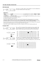
If the ON settings are Monday 13:00 and the OFF settings are Wednesday 18:00, output D1 turns on and off as follows.
When the WEEK instruction input is ON on Monday 13:00, output D1 turns ON on Monday 13:00 and it turns OFF on Wednesday
18:00.
(In this diagram the WEEK instruction input is turned on at 0:00 on Monday)
Notes:
• A maximum of 10 WEEK instructions can be used in a user program.
• Normally the output is only updated when the current time and the time for the ON/OFF settings matches, but when the WEEK instruction input
changes from off to on, the output state at the current time is determined according to the ON/OFF settings and the output is turned on or off.
For details, see "Timing Chart when the Input Turns On during the Configured Interval" on page 11-10.
• When pulse output is enabled, output is turned on for one scan at the ON settings time. For pulse output, see "6. Pulse Output" on page 11-
5 or "6. Pulse Output" on page 11-8.
• When the ON time is set to a value larger than 2,359, the OFF time is set to a value larger than 2,400, or the lower 2 digits of ON/OFF time
is set to a value larger than 59, a user program execution error will occur.
• When the day of the week is not specified, a user program execution error will occur.
• The WEEK instruction cannot be used in an interrupt program. If used, a user program execution error will result, turning on special internal
relay M8004 and the ERR LED on the FC6A Series MICROSmart. For details about the user program execution errors, see "User Program
Execution Errors" on page 3-10.
Valid Devices
Special data registers cannot be designated as S1. Special internal relays cannot be designated as D1.
The WEEK instruction compares the specified day of the week, ON time, and OFF
time with the current time and outputs that result.
When the input is on, the output specified by D1 is turned on when the day of the
week and the time specified by the ON settings match the current day of the
week and time.
The output specified by D1 is also turned off when the day of the week and the
time specified by the OFF settings match the current day of the week and time.
D1
*****
S2
*****
WEEK
S1
*****
S3
*****
Device
Function
I
Q
M
R
T
C
D
P
Constant
Repeat
S1 (Source 1)
First data register
—
—
—
—
—
—
—
—
—
S2 (Source 2)
Initialization input
—
—
X
—
—
—
—
—
—
—
S3 (Source 3)
Number of parameter tabs
—
—
—
—
—
—
—
—
X
—
D1 (Destination 1)
Output port
—
X
—
—
—
—
—
—
—
ON
OFF
ON
OFF
Output Q0
Input M0000
Sunday
Monday
Tuesday
Wednesday
Thursday
Friday
Saturday
Day of the week
Time
ON settings Day of the week : Monday
Time : 13:00
OFF settings Day of the week : Wednesday
Time : 18:00
18:00
13:00
0:00
Summary of Contents for MICROSmart FC6A Series
Page 1: ...B 1726 7 FC6A SERIES Ladder Programming Manual ...
Page 8: ...Preface 7 FC6A SERIES MICROSMART LADDER PROGRAMMING MANUAL FC9Y B1726 ...
Page 32: ...1 OPERATION BASICS 1 20 FC6A SERIES MICROSMART LADDER PROGRAMMING MANUAL FC9Y B1726 ...
Page 96: ...3 INSTRUCTIONS REFERENCE 3 18 FC6A SERIES MICROSMART LADDER PROGRAMMING MANUAL FC9Y B1726 ...
Page 130: ...4 BASIC INSTRUCTIONS 4 34 FC6A SERIES MICROSMART LADDER PROGRAMMING MANUAL FC9Y B1726 ...
Page 192: ...9 SHIFT ROTATE INSTRUCTIONS 9 12 FC6A SERIES MICROSMART LADDER PROGRAMMING MANUAL FC9Y B1726 ...
Page 272: ...12 DISPLAY INSTRUCTIONS 12 24 FC6A SERIES MICROSMART LADDER PROGRAMMING MANUAL FC9Y B1726 ...
Page 284: ...14 REFRESH INSTRUCTIONS 14 6 FC6A SERIES MICROSMART LADDER PROGRAMMING MANUAL FC9Y B1726 ...
Page 502: ...25 DATA LOG INSTRUCTIONS 25 22 FC6A SERIES MICROSMART LADDER PROGRAMMING MANUAL FC9Y B1726 ...
Page 546: ...26 SCRIPT 26 44 FC6A SERIES MICROSMART LADDER PROGRAMMING MANUAL FC9Y B1726 ...
Page 598: ...APPENDIX A 14 FC6A SERIES MICROSMART LADDER PROGRAMMING MANUAL FC9Y B1726 ...


