FC6A S
ERIES
MICROS
MART
L
ADDER
P
ROGRAMMING
M
ANUAL
FC9Y-B1726
19-7
19: PID C
ONTROL
I
NSTRUCTION
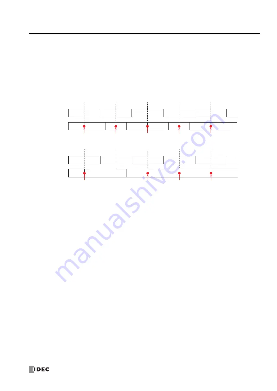
6. Sampling Period (S1+5)
Set the cycle to execute the PID control.
PID control will only be executed at the end of the scan.
When the sampling period is set lower than the scan time, PID control is not executed with the set sampling period, it will be
executed with the same period as the scan time.
When the sampling period is set longer than the scan time, if the scan has not finished when the sampling period has elapsed,
PID control will wait until the scan ends and then be executed.
Due to the above factors, an error will occur between the sampling period and the actual PID control execution timing.
The sampling period can be set from 0.01 to 100.00 seconds in 0.01 second increments.
Sampling period
≤
Scan time
Sampling period > Scan time
7. Advanced/Basic
Click this button to show or hide the advanced settings.
On the
Input
tab, Sampling Period (6) can be set as an advanced setting.
8. Alarm 1 (Process High Alarm) (S1+3)
Set the upper limit value of the process variable (1).
The alarm 1 value can be set in the range between the alarm 2 value (process low alarm) (9) and the maximum value (4).
If the process variable is higher than or equal to the alarm 1 value, the alarm 1 output (S3+3) turns on.
If the process variable is lower than the alarm 1 value, the alarm 1 output (S3+3) turns off.
9. Alarm 2 (Process Low Alarm) (S1+4)
Set the lower limit value of the process variable (1).
The alarm 2 value can be set in the range between the minimum value (5) and the alarm 1 value (process high alarm) (8).
If the process variable is lower than or equal to the alarm 2 value, the alarm 2 output (S3+4) turns on.
If the process variable is higher than the alarm 2 value, the alarm 2 output (S3+4) turns off.
A maximum of four alarms (Alarm 3 to Alarm 6) can be configured for the process variable in PID control.
Individually configure Alarm Type (10), Alarm Value (11), Hysteresis (12), and Delay Time (13).
PID control
executed
PIDA instruction executed
Scan time
(
60 ms
)
Sampling period
(
40 ms
)
0 ms
PIDA instruction executed
60 ms
PIDA instruction executed
120 ms
PIDA instruction executed
180 ms
PIDA instruction executed
240 ms
240 ms
0 ms
80 ms
PID control executed
PID control executed
PID control executed
PID control executed
160 ms
160 ms
160 ms
PID control executed
0 ms
60 ms
120 ms
180 ms
240 ms
240 ms
0 ms
80 ms
PID control executed
PID control executed
PID control executed
Scan time
(60 ms)
Sampling period
(40 ms)
PIDA instruction executed PIDA instruction executed PIDA instruction executed PIDA instruction executed PIDA instruction executed
160 ms
160 ms
160 ms
Summary of Contents for MICROSmart FC6A Series
Page 1: ...B 1726 7 FC6A SERIES Ladder Programming Manual ...
Page 8: ...Preface 7 FC6A SERIES MICROSMART LADDER PROGRAMMING MANUAL FC9Y B1726 ...
Page 32: ...1 OPERATION BASICS 1 20 FC6A SERIES MICROSMART LADDER PROGRAMMING MANUAL FC9Y B1726 ...
Page 96: ...3 INSTRUCTIONS REFERENCE 3 18 FC6A SERIES MICROSMART LADDER PROGRAMMING MANUAL FC9Y B1726 ...
Page 130: ...4 BASIC INSTRUCTIONS 4 34 FC6A SERIES MICROSMART LADDER PROGRAMMING MANUAL FC9Y B1726 ...
Page 192: ...9 SHIFT ROTATE INSTRUCTIONS 9 12 FC6A SERIES MICROSMART LADDER PROGRAMMING MANUAL FC9Y B1726 ...
Page 272: ...12 DISPLAY INSTRUCTIONS 12 24 FC6A SERIES MICROSMART LADDER PROGRAMMING MANUAL FC9Y B1726 ...
Page 284: ...14 REFRESH INSTRUCTIONS 14 6 FC6A SERIES MICROSMART LADDER PROGRAMMING MANUAL FC9Y B1726 ...
Page 502: ...25 DATA LOG INSTRUCTIONS 25 22 FC6A SERIES MICROSMART LADDER PROGRAMMING MANUAL FC9Y B1726 ...
Page 546: ...26 SCRIPT 26 44 FC6A SERIES MICROSMART LADDER PROGRAMMING MANUAL FC9Y B1726 ...
Page 598: ...APPENDIX A 14 FC6A SERIES MICROSMART LADDER PROGRAMMING MANUAL FC9Y B1726 ...


