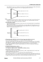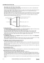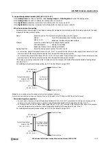
19: PID C
ONTROL
I
NSTRUCTION
19-24
FC6A S
ERIES
MICROS
MART
L
ADDER
P
ROGRAMMING
M
ANUAL
FC9Y-B1726
■
PID control
PID controls overshooting and hunting in Proportional control, corrects the offset in I (integral) control, and makes rapid
temperature changes due to disturbances converge on the set point in a short amount of time in D (derivative) control. Ideal
temperature control can be performed by using PID control. The parameters for the proportional band, integral time, and
derivative time in PID control can be automatically set with auto tuning.
Auto Tuning (AT)
Optimal temperature control parameters will differ according to the characteristics of the subject to control. When performing PID
control, the proportional band (P), integral time (I), and derivative time (D) can be automatically set by executing auto tuning.
• Perform auto tuning during test operation.
• When auto tuning is executed near normal temperatures, temperature fluctuations cannot be imposed, so auto tuning may not end normally.
In such cases, set the values for P, I, and D manually.
• When auto turning is executed once, so long as the process is not changed, it is not necessary to execute auto tuning again.
■
Auto tuning (AT)
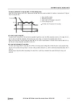
In order to automatically set the proportional band (P), integral time (I), and derivative time (D), fluctuations must be forcibly
imposed on the subject to control to set each value to the optimal value. In order to perform optimal auto tuning, fluctuations
must be imposed when the process variable has reached a value near the set point. Fluctuations can be imposed when the process
variable is near the set point by setting the AT bias. The relationship between the set point, AT bias, auto tuning start point, and
fluctuation start point is as follows.
Process variable (PV)
≤
set point (SP) - AT bias setting value
When the AT bias setting is set to 20°C, fluctuations will start when the process variable (PV) reaches a temperature 20°C lower
than the set point (SP).
Set point (SP) - AT bias setting value < process variable (PV) < set point (SP) + AT bias setting value
Fluctuations will start when the process variable (PV) reaches the set point (SP).
Temperature
Set point
Disturbance
Time
1. Measuring PID constants
2. Calculate PID constants
3. Control with the PID constants set with AT
4. AT bias setting value (20)
AT: When the AT execution bit is turned on
1. Measuring PID constants
2. Calculate PID constants
3. Control with the PID constants set with AT
4. AT bias setting value (20)
AT: When the AT execution bit is turned on
Temperature
SP
SP-20
Proportional band
AT
1
4
2
3
Time
Temperature
SP
SP-20
SP+20
Proportional band
AT
1
4
4
2
3
Time
Summary of Contents for MICROSmart FC6A Series
Page 1: ...B 1726 7 FC6A SERIES Ladder Programming Manual ...
Page 8: ...Preface 7 FC6A SERIES MICROSMART LADDER PROGRAMMING MANUAL FC9Y B1726 ...
Page 32: ...1 OPERATION BASICS 1 20 FC6A SERIES MICROSMART LADDER PROGRAMMING MANUAL FC9Y B1726 ...
Page 96: ...3 INSTRUCTIONS REFERENCE 3 18 FC6A SERIES MICROSMART LADDER PROGRAMMING MANUAL FC9Y B1726 ...
Page 130: ...4 BASIC INSTRUCTIONS 4 34 FC6A SERIES MICROSMART LADDER PROGRAMMING MANUAL FC9Y B1726 ...
Page 192: ...9 SHIFT ROTATE INSTRUCTIONS 9 12 FC6A SERIES MICROSMART LADDER PROGRAMMING MANUAL FC9Y B1726 ...
Page 272: ...12 DISPLAY INSTRUCTIONS 12 24 FC6A SERIES MICROSMART LADDER PROGRAMMING MANUAL FC9Y B1726 ...
Page 284: ...14 REFRESH INSTRUCTIONS 14 6 FC6A SERIES MICROSMART LADDER PROGRAMMING MANUAL FC9Y B1726 ...
Page 502: ...25 DATA LOG INSTRUCTIONS 25 22 FC6A SERIES MICROSMART LADDER PROGRAMMING MANUAL FC9Y B1726 ...
Page 546: ...26 SCRIPT 26 44 FC6A SERIES MICROSMART LADDER PROGRAMMING MANUAL FC9Y B1726 ...
Page 598: ...APPENDIX A 14 FC6A SERIES MICROSMART LADDER PROGRAMMING MANUAL FC9Y B1726 ...


