FC6A S
ERIES
MICROS
MART
L
ADDER
P
ROGRAMMING
M
ANUAL
FC9Y-B1726
25-15
25: D
ATA
L
OG
I
NSTRUCTIONS
TRACE (Data Trace)
The filename of created CSV files is as follows:
• All-in-One CPU module:
The CSV file name is "DATE.csv." The date when the DLOG instruction is turned on is used as DATE.
Example: When the date is December 30, 2015, the file name is "20151230.csv".
• Plus CPU module:
A new folder "YYYYMMDD" (Year, Month, and Date) is created and csv files are stored in the folder. Underscore "_" and 2-digit
number "00 to 99" are appended to the csv filenames. When the file size exceeds the log data file size, a new file is created and
2-digit number is incremented and appended to the filename.
Example: When the date is April 1, 2017 and the first file in the day is created, the file is "20170401
\
20170401_00.csv."
When a CSV file with the same date does not exist in the folder designated by S1, the CSV file is created and the trace data is
output. The oldest data is output at the top of the trace data, and the latest data is output at the bottom of the trace data.
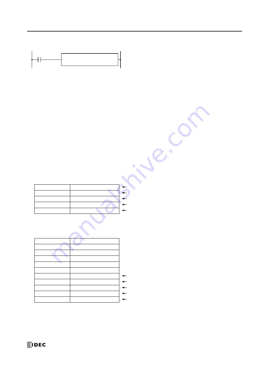
Output example
When a CSV file for the same date already exists in the folder designated by S1, the header and trace data are appended to the
CSV file.
Output example
When the execution of the TRACE instruction finishes, the device designated by D1 is turned on and the status code is stored to
the device designated by D2 according to the execution result. For status codes, see "3. D2 (destination 2): Execution Status" on
page 25-17.
The TRACE instruction saves the values for the previous number of scans for the
specified device in the specified data format as a CSV file on the SD memory card.
When the input is turned on, the date and time and the values of the previous
scans for the specified device are output to the CSV file in the folder assigned by
S1. When the execution of the instruction finishes, the device assigned by D1 is
turned on and the execution status is stored to the device assigned by D2.
When the folder assigned by S1 does not exist on the SD memory card, that
folder is created. The folder path is "FCDATA01
\
TRACE
\
User specified folder." For
details on the folder structure, see Chapter 11 "SD Memory Card" in the "FC6A
Series MICROSmart User’s Manual".
D1
*****
S1
*****
TRACE
D2
*****
Triggered at:
2012/02/06 08:30:23
Header row 1
Scan
D0010
Header row 2
Old
12345
Data 2 scans before
12345
Data 1 scan before
New
12345
Latest data
Triggered at:
2012/02/06 08:30:23
Scan
D0010
Old
12345
12345
New
12345
Triggered at:
2012/02/06 17:16:15
Appended header row 1
Scan
D0010
Appended header row 2
Old
1212
Appended data 2 scans before
1212
Appended data 1 scan before
New
1212
Appended latest data
Summary of Contents for MICROSmart FC6A Series
Page 1: ...B 1726 7 FC6A SERIES Ladder Programming Manual ...
Page 8: ...Preface 7 FC6A SERIES MICROSMART LADDER PROGRAMMING MANUAL FC9Y B1726 ...
Page 32: ...1 OPERATION BASICS 1 20 FC6A SERIES MICROSMART LADDER PROGRAMMING MANUAL FC9Y B1726 ...
Page 96: ...3 INSTRUCTIONS REFERENCE 3 18 FC6A SERIES MICROSMART LADDER PROGRAMMING MANUAL FC9Y B1726 ...
Page 130: ...4 BASIC INSTRUCTIONS 4 34 FC6A SERIES MICROSMART LADDER PROGRAMMING MANUAL FC9Y B1726 ...
Page 192: ...9 SHIFT ROTATE INSTRUCTIONS 9 12 FC6A SERIES MICROSMART LADDER PROGRAMMING MANUAL FC9Y B1726 ...
Page 272: ...12 DISPLAY INSTRUCTIONS 12 24 FC6A SERIES MICROSMART LADDER PROGRAMMING MANUAL FC9Y B1726 ...
Page 284: ...14 REFRESH INSTRUCTIONS 14 6 FC6A SERIES MICROSMART LADDER PROGRAMMING MANUAL FC9Y B1726 ...
Page 502: ...25 DATA LOG INSTRUCTIONS 25 22 FC6A SERIES MICROSMART LADDER PROGRAMMING MANUAL FC9Y B1726 ...
Page 546: ...26 SCRIPT 26 44 FC6A SERIES MICROSMART LADDER PROGRAMMING MANUAL FC9Y B1726 ...
Page 598: ...APPENDIX A 14 FC6A SERIES MICROSMART LADDER PROGRAMMING MANUAL FC9Y B1726 ...


