3: I
NSTRUCTIONS
R
EFERENCE
3-6
FC6A S
ERIES
MICROS
MART
L
ADDER
P
ROGRAMMING
M
ANUAL
FC9Y-B1726
Structure of an Advanced Instruction
Input Condition for Advanced Instructions
Almost all advanced instructions must be preceded by a contact, except NOP (no operation), LABEL (label), and LRET (label
return) instructions. The input condition can be programmed using a bit device such as input, output, internal relay, or shift
register. Timer and counter can also be used as an input condition to turn on the contact when the timer times out or the counter
counts out.
While the input condition is off, the advanced instruction is not executed and device statuses are held.
Source and Destination Devices
The source and destination devices specify 16- or 32-bit data, depending on the selected data type. When a bit device such as
input, output, internal relay, or shift register is designated as a source or destination device, 16 or 32 points starting with the
designated number are processed as source or destination data. When a word device such as timer or counter is designated as a
source device, the current value is read as source data. When a timer or counter is designated as a destination device, the result
of the advanced instruction is set to the preset value for the timer or counter. When a data register is designated as a source or
destination device, the data is read from or written to the designated data register.
Using Timer or Counter as Source Device
Since all timer instructions—TML (1-s timer), TIM (100-ms timer), TMH (10-ms timer), and TMS (1-ms timer)—subtract from the
preset value, the current value is decremented from the preset value and indicates the remaining time. As described above, when
a timer is designated as a source device of an advanced instruction, the current value, or the remaining time, of the timer is read
as source data. Adding counters CNT start counting at 0, and the current value is incremented up to the preset value. Reversible
counters CDP and CUD start counting at the preset value and the current value is incremented or decremented from the preset
value. When any counter is designated as a source device of an advanced instruction, the current value is read as source data.
Using Timer or Counter as Destination Device
As described above, when a timer or counter is designated as a destination device of an advanced instruction, the result of the
advanced instruction is set to the preset value of the timer or counter. Timer and counter preset values can be 0 through 65,535.
When a timer or counter preset value is designated using a data register, the timer or counter cannot be designated as a
destination of an advanced instruction. When executing such an advanced instruction, a user program execution error will
result. For details of user program execution error, see "User Program Execution Error" on page A-12.
Note:
When a user program execution error occurs, the result is not set to the destination.
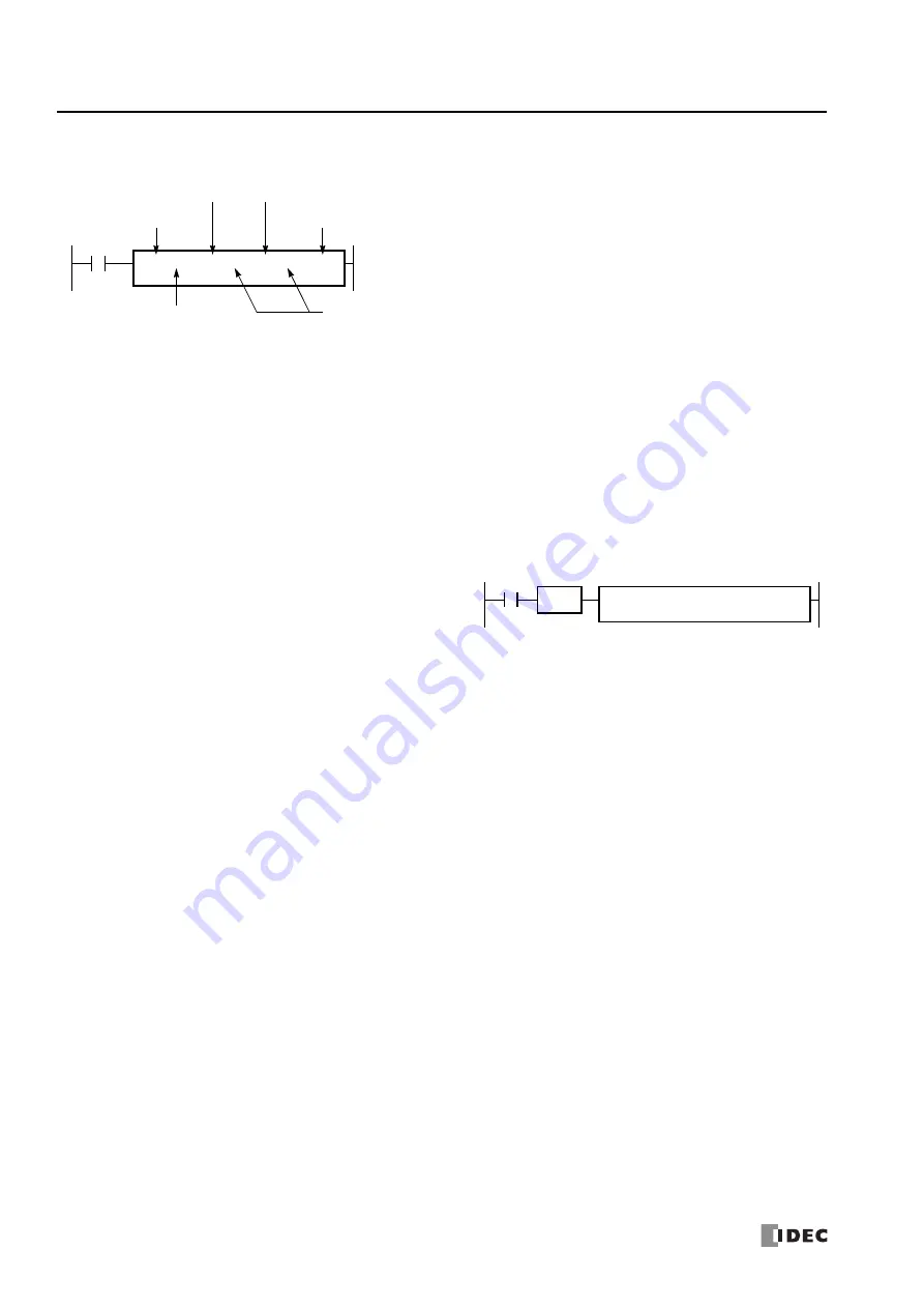
Repeat Designation
Specifies whether repeat is used for the device or not.
Repeat Cycles
Specifies the quantity of repeat cycles: 1 through 99.
Opcode
The opcode is a symbol used to identify the advanced instruction.
Data Type
Specifies word (W), integer (I), double word (D), long (L), or float
(F) data.
Source Device
The source device specifies the 16- or 32-bit data to be processed
by the advanced instruction. Some advanced instructions require
two source devices.
Destination Device
The destination device specifies the 16- or 32-bit data to store the
result of the advanced instruction. Some advanced instructions
require two destination devices.
I0
S1 R
*****
REP
**
D1 R
*****
Opcode
Source Device
Repeat Cycles
Destination Device
Repeat
MOV(W)
Data Type
Designation
While the input condition is on, the advanced instruction is
executed in each scan. To execute the advanced instruction
only at the rising or falling edge of the input, use the SOTU or
SOTD instruction.
I0
REP
S1 –
D10
D1 –
D20
SOTU
MOV(W)
Summary of Contents for MICROSmart FC6A Series
Page 1: ...B 1726 7 FC6A SERIES Ladder Programming Manual ...
Page 8: ...Preface 7 FC6A SERIES MICROSMART LADDER PROGRAMMING MANUAL FC9Y B1726 ...
Page 32: ...1 OPERATION BASICS 1 20 FC6A SERIES MICROSMART LADDER PROGRAMMING MANUAL FC9Y B1726 ...
Page 96: ...3 INSTRUCTIONS REFERENCE 3 18 FC6A SERIES MICROSMART LADDER PROGRAMMING MANUAL FC9Y B1726 ...
Page 130: ...4 BASIC INSTRUCTIONS 4 34 FC6A SERIES MICROSMART LADDER PROGRAMMING MANUAL FC9Y B1726 ...
Page 192: ...9 SHIFT ROTATE INSTRUCTIONS 9 12 FC6A SERIES MICROSMART LADDER PROGRAMMING MANUAL FC9Y B1726 ...
Page 272: ...12 DISPLAY INSTRUCTIONS 12 24 FC6A SERIES MICROSMART LADDER PROGRAMMING MANUAL FC9Y B1726 ...
Page 284: ...14 REFRESH INSTRUCTIONS 14 6 FC6A SERIES MICROSMART LADDER PROGRAMMING MANUAL FC9Y B1726 ...
Page 502: ...25 DATA LOG INSTRUCTIONS 25 22 FC6A SERIES MICROSMART LADDER PROGRAMMING MANUAL FC9Y B1726 ...
Page 546: ...26 SCRIPT 26 44 FC6A SERIES MICROSMART LADDER PROGRAMMING MANUAL FC9Y B1726 ...
Page 598: ...APPENDIX A 14 FC6A SERIES MICROSMART LADDER PROGRAMMING MANUAL FC9Y B1726 ...


