background image

10

PS5R-V Switching Power Supplies

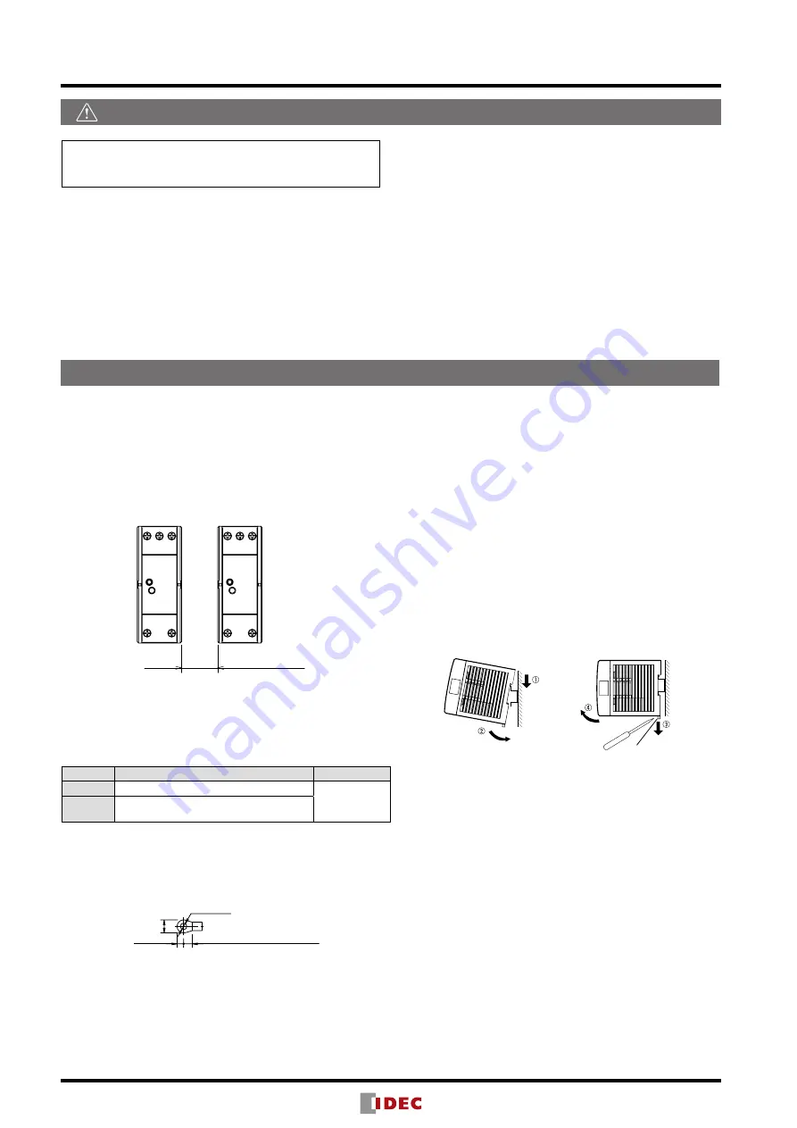
Mounting on DIN Rails

1. Use a 35mm-wide DIN rail.
2. Fasten the DIN rail to a mounting plate using screws.
3. Place the PS5R-V on the DIN rail as shown with input termi-

nal side up (

), and press the PS5R-V towards the DIN rail  

(

). Make sure that the PS5R-V is installed firmly.

4. Use BNL6 mounting clips for fastening the PS5R-V on the 

DIN rail. Use of BNL8 mounting clips is recommended when 

excessive vibration or shock is anticipated. Do not use the 

PS5R-V when it is subject to vibration constantly.

Removal

• Insert a flat screwdriver into the slot in the clamp, and pull out 

the clamp until it clicks (

). The lock mechanism is released 

and the PS5R-V can be removed (

). When mounting the 

PS5R-V again, push in the latch first.

Notes for installation

• Do not close the top and bottom openings of the PS5R-V to 

allow for heat radiation by convection.

• Maintain a minimum of 10 mm clearance around the PS5R-V, 

except for the top and bottom openings.

• When mounting multiple PS5R-V switching power supplies 

side by side, maintain a minimum of 10 mm clearance. Ob-

serve the derating curves in consideration of the ambient 

temperature.

10mm minimum

• When the derating voltage may exceed the recommended 

value, provide forced air-cooling.

• Make sure to wire the ground terminal correctly.
• For wiring, use wires of heat resistance of 60oC or higher 

(PS5R-VB: 80oC or higher). Use copper wire of the following 

sizes, according to the rated current.

Terminal

Wire Size (allowable current)

Wire Type

Input

AWG18 to 14

Copper 
Solid/Stranded

Output

AWG18 to 14 

(AWG18: 7A, AWG16: 10A, AWG14: 15A)

Cross-sectional area

AWG18: 0.82mm

2

, AWG16: 1.31mm

2

, AWG14: 2.0mm

2

Note: Wires of the above size must be used to comply with 

UL508, CSA C22.2 No. 107.1.

Applicable crimp terminal (reference)

7.0 max.


4.1 max.

5.6 min. (PS5R-VG: 6.3 min)

ø3.6 min.

• Recommended tightening torque of the input and output ter-

minals is 1.0 to 1.3 N·m (0.8 N·m for UL).

 Safety Precautions

Operating Instructions

Mount the PS5R-V in an enclosure. Do not use the PS5R-V 

alone as an Electric Facilities for General Use.
Use the PS5R-V for electric facilities for business use only.

• Do not use switching power supplies with electric equipment 

whose malfunction or inadvertent operation may damage the hu-

man body or life directly.

• Make sure that the input voltage and output current do not ex-

ceed the ratings. If the input voltage and output current exceed 

the ratings, electric shock, fire, or malfunction may occur.

• Do not touch the terminals of the switching power supply while 

input voltage is applied, otherwise electric shock may occur.

• Provide the final product with protection against malfunction or 

damage that may be caused by malfunction of the switching 

power supply.

• Operating temperatures should not exceed the ratings. Be sure to 

note the derating characteristics. If the operating temperature ex-

ceeds the ratings, electric shock, fire, or malfunction may occur.

• Blown fuses indicate that the internal circuits are damaged. Con-

tact IDEC for repair. Do not just replace the fuse and reoperate, 

otherwise electric shock, fire, or malfunction may occur.

• Do not use the switching power supplies to charge rechargeable 

batteries.

• Do not overload or short-circuit the switching power supply for 

a long period of time, otherwise the internal elements may be 

damaged.

• Do not disassemble, repair, or modify the power supplies, other-

wise the high voltage internal part may cause electric shock, fire, 

or malfunction.

• The fuse inside the PS5R-V switching power supply is for AC 

input. Use a DC fuse for DC input.

Mounting

Removal

Clamp

Summary of Contents for PS5R-V Series

Page 1: ...PS5R V Switching Power Supplies ...

Page 2: ...1 Improved reliability Reduces installation space inside the panel Reduced wiring flexible installation Suitable for global and semiconductor applications Spring up terminals accepts wiring of ring terminals No need to worry about loosing screws Six mounting directions Compliant with International Safety Standards Meets SEMI F47 Sag Immunity 208V AC input Voltage sag ride through capabilities for ...

Page 3: ...R VB VC VD VE only 2 EN60950 1 EN50178 only PS5R V Package Quantity 1 Output Capacity Part No Input Voltage Output Voltage Output Current 10W PS5R VB05 100 to 240V AC Voltage range 85 to 264V AC 100 to 370V DC 5V 2 0A 15W PS5R VB12 12V 1 3A PS5R VB24 24V 0 65A 30W PS5R VC12 12V 2 5A PS5R VC24 24V 1 3A 60W PS5R VD24 24V 2 5A 90W PS5R VE24 24V 3 75A 120W PS5R VF24 24V 5 0A 240W PS5R VG24 24V 10 0A D...

Page 4: ...1 min auto reset 105 min auto reset Operation Indicator LED green Dielectric Strength Between input and output terminals 3 000V AC 1 minute Between input and ground terminals 2 000V AC 1 minute Between output and ground terminal 500V AC 1 minute Insulation Resistance Between input and output terminals 100MΩ min 500V DC megger Between input and ground terminal 100MΩ min 500V DC megger Operating Tem...

Page 5: ...ter Overcurrent Detection PS5R VE24 L N INPUT V ADJ V V Switching Control Detection Fuse Rectifying Active Filter Ripple Filter Rectifying Line filter Overcurrent Detection PS5R VF24 L N INPUT V ADJ V V Switching Control Detection Fuse Rectifying Rectifying Active Filter Ripple Filter Line filter Overcurrent Detection PS5R VG24 L N INPUT V ADJ V V Switching Control Detection Fuse Rectifying Active...

Page 6: ...t Current Output Current Output Current Output Current Output Current Mounting F Mounting C E 30 20 10 0 10 20 30 40 50 60 70 80 0 10 20 30 40 50 60 70 80 90 100 Mounting B D Mounting A Operating Temperature C Output Current 30 20 10 0 10 20 30 40 50 60 70 80 0 10 20 30 40 50 60 70 80 90 100 30 20 10 0 10 20 30 40 50 60 70 80 0 10 20 30 40 50 60 70 80 90 100 Operating Temperature Approved by Safet...

Page 7: ...t terminal V Negative output terminal VR ADJ Output Voltage Adjustment Turning clockwise increases the output voltage Turning counterclockwise decreases the output voltage DC ON Operation Indicator green Lights when the output voltage is on Overcurrent Protection Characteristics 30 0 100 0 100 0 0 100 95 0 0 100 95 100 100 105 and over 105 and over 101 and over Output Current Output Current Output...

Page 8: ...125 3 8 115 98 8 5 46 23 11 5 11 5 4 5 44 9 35 3 3 8 121 36 95 79 8 20 10 10 108 3 8 4 5 24 9 35 3 3 8 95 4 4 35 3 27 3 61 6 12 2 8 2 90 9 5 22 5 5 M3 5 Screw Terminal 5 M3 5 Screw Terminal 5 M3 5 Screw Terminal 5 M3 5 Screw Terminal PS5R VD VE PS5R VF PS5R VG PS5R VB VC All dimensions in mm Tolerance 1mm ...

Page 9: ...e View Front View Side View Side View Back View Mounting Screws 4 M3 6 countersunk screws 13 6 16 4 96 7 5 5 28 8 10 0 10 0 12 112 102 26 105 10 2 9 9 109 8 12 24 7 112 120 102 0 110 44 62 9 26 38 105 115 36 48 125 135 36 125 10 2 9 9 122 8 135 145 28 39 28 135 28 10 5 10 5 145 10 130 6 56 138 6 56 148 6 138 6 56 70 62 3 29 5 11 8 31 11 8 2 M4 or ø2 4 5 holes 2 M4 or ø2 4 5 holes 2 M4 or ø2 4 5 ho...

Page 10: ...e used to comply with UL508 CSA C22 2 No 107 1 Applicable crimp terminal reference 7 0 max 4 1 max 5 6 min PS5R VG 6 3 min ø3 6 min Recommended tightening torque of the input and output ter minals is 1 0 to 1 3 N m 0 8 N m for UL Safety Precautions Operating Instructions Mount the PS5R V in an enclosure Do not use the PS5R V alone as an Electric Facilities for General Use Use the PS5R V for electr...

Page 11: ...ops automatically when an overcurrent flows due to an overload or short circuit Normal voltage is auto matically restored when the load returns to normal condi tions Insulation Dielectric Test When performing an insulation dielectric test short circuit the input between L and N and output between V and V Do not apply or interrupt the voltage quickly otherwise surge volt ages may be generated and t...

Page 12: ...nditions The maximum value of output capacity is within the range shown in Operating Temperature vs Output Current on page 5 1 Average operating temperature ambient temperature of switching power supply is 40 C maximum 2 The load is 80 maximum 3 Input voltage is the rated input voltage 4 Standard mounting style IDEC shall not be liable for other damages including conse quential contingent or incid...

Reviews: