185
800-262-IDEC
(4332)
•
USA & Canada
SA1E
Sensors
OI T
ouchscreens
PLCs
Automation Software
Power Supplies
Sensors
Communication
Barriers
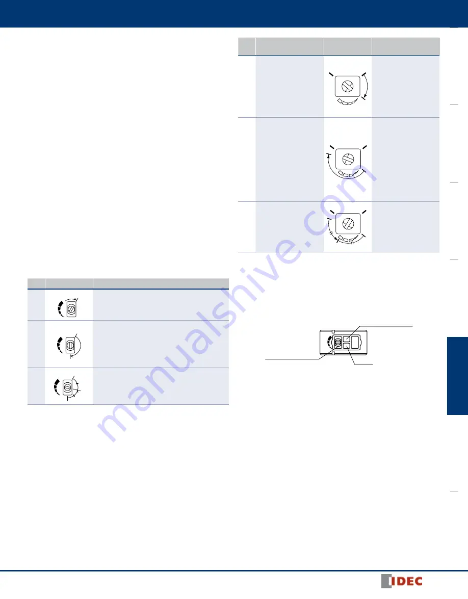
3. Sensitivity Adjustment
•
Referring to the table to the right, adjust the sensitivity of the SA1E photo-
electric switch when necessary, in such cases as the through-beam type is
used to detect small or translucent objects or the reflective type is affected by
background. The table explains the status of operation LED when the opera-
tion mode is set to light ON.
•
After adjusting the sensitivity, make sure that stable LED turns on at stable
incident and stable interruption. For detecting objects too small to turn on the
stable LED, use an optional slit.
•
Sensitivity is set to the maximum at the factory before shipment. When
adjusting the sensitivity, use the screwdriver supplied with the SA1E photo-
electric switch to turn the control as shown below, to a torque of 0.05 N·m
maximum.
Step
Photoelectric
Switch Status
Sensitivity
Control
Adjusting Procedure
1
Receiving light
•
Through-beam, polarized
reflective: No object
detected
•
Diffuse reflective,
small-beam reflec tive,
convergent reflective:
Object detected
max.
min.
A
Turn the control counter-
clockwise to the mini mum.
Then turn clock wise until
the operation LED turns
on (turns off with dark ON
type) (point A).
2
Light is interrupted
•
Through-beam, polar-
ized reflective: Object
detected
•
Diffuse reflective,
small-beam reflec tive,
convergent reflective:
No object detected
B
A
max.
min.
At interruption status, turn
the control clock wise from
point A, until the operation
LED turns on (turns off with
dark ON type) (point B).
If the operation LED does
not turn on (turn off with
dark ON type) even though
the control has reached the
maxi mum, set the maxi-
mum position as point B.
3
–
C
B
A
max.
min.
Set the middle point
between point A and B as
point C.
4. Adjustment of Sensing Range for Background Suppression (BGS) Type
•
When adjusting the sensing range, follow the instructions below.
Step Distance Control
Adjusting Procedure
1
A
Turn the control counter-clockwise to the mini mum. Then
turn clock wise until the operation LED turns on (turns off
with dark ON type) (point A).
2
A
B
At interruption status, turn the control clock wise from
point A, until the operation LED turns on (turns off with
dark ON type) (point B).
If the operation LED does not turn on (turn off with dark
ON type) even though the control has reached the maxi-
mum, set the maximum position as point B.
3
A
B
C
Set the middle point between point A and B as point C.
1. When the background is far off and not detected, turn the control 360°, and set the point as point C.
2. Because the control is multi-turn, it may take more than one turn to move from point A to point B.
3. Turning the control clockwise lengthens the sensing dis tance.
4. Background suppression (BGS) type is not provided with a stable LED.
Operation LED (yellow)
(Note 3)
Sensing Range Control
(6-turn)
(Note 4)
5. Power Supply and Wiring
•
Do not use the SA1E photoelectric switch at the transient status immediately
after turning on the power (approx. 100 ms, back ground suppression type: 200
ms). When the load and switch use different power supplies, make sure to
power up the switch first.
•
Use a power supply with little noise and inrush current, and use the photo-
electric switch within the rated voltage range. Make sure that ripple factor is
within the allowable limit. Do not apply AC volt age, otherwise the switch may
blow out or burn.
•
When using a switching power supply, make sure to ground the FG (frame
ground) terminal, otherwise high-frequency noise may affect the photoelectric
switch.
•
Turn power off before inserting/removing the connector on photo electric
switch. Make sure that excessive mechanical force is not applied to the
connector. Connect the connector cable to a tight ening torque of 0.5 N·m
maximum.
•
To ensure the degree of protection, use the applicable connector cable for the
connector type. Connector cables are ordered sepa rately.
•
Avoid parallel wiring with high-voltage or power lines in the same conduit,
otherwise noise may cause malfunction and damage. When wiring is long,
use a separate conduit for wiring.
•
Use a cable of 0.3 mm
2
minimum core wires, then the cable can be extended
up to 100m.


