SE2L User’s Manual (SE9Z-B1865)
89
7.7.3 Mode
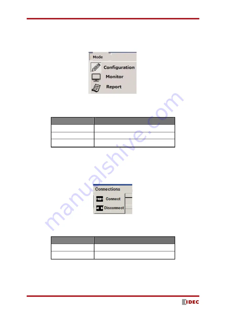
This menu is used for changing the mode of the SE2L. Items in the menu are shown in Figure 7-23. Function
of each mode as shown in the Table 7-5.
Figure 7-23 Mode
Table 7-5 Mode
Item
Function
Configuration mode
Configure the SE2L settings
Monitor mode
Monitor the SE2L operation.
Report
View SE2L setting and error information
7.7.4 Connection
When connection is clicked, items as shown in the figure 7-24 will be displayed. Table 7-6 shows the
details of each item. When SE2L is not connected these items are in gray and cannot be selected.
Figure 7-24 Connection
Table 7-6 Connection
Item
Function
Connect
Connects to SE2L
Disconnect
Disconnects SE2L
Summary of Contents for SE2L Series
Page 1: ...SE9Z B1865 SE2L Series Safety Laser Scanner User s Manual ...
Page 100: ...SE2L User s Manual SE9Z B1865 99 Figure 7 31 b Function Figure7 31 c Area ...
Page 143: ...SE2L User s Manual SE9Z B1865 142 13 External dimension 13 1 SE2L H05LP mm ...
Page 144: ...SE2L User s Manual SE9Z B1865 143 13 2 SE2L H05LPC mm ...
Page 145: ...SE2L User s Manual SE9Z B1865 144 13 3 Base mounting bracket mm ...
Page 146: ...SE2L User s Manual SE9Z B1865 145 13 4 Rear mounting bracket mm ...
Page 147: ...SE2L User s Manual SE9Z B1865 146 13 5 Simple base mounting bracket mm ...
Page 149: ...SE2L User s Manual SE9Z B1865 148 13 7 Simple rear mounting bracket Long type mm ...
Page 150: ...SE2L User s Manual SE9Z B1865 149 13 8 Cover Protection Bracket mm ...


