background image

2-1

Operational Check

This chapter describes the system requirements, setup, and how to test operation of the WB2F Support Tool.

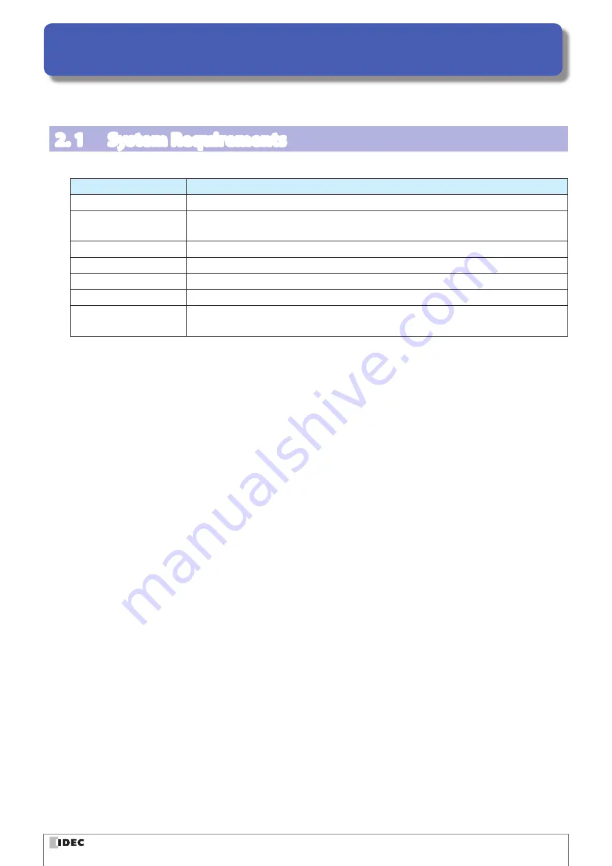
2. 1  System Requirements

This table shows the WB2F Support Tool system requirements.

Item

Details

PC

PC-AT or compatible

OS

Windows 7 (32-/64-bit), Windows 8 (32-/64-bit),
Windows 8.1 (32-/64-bit), Windows 10 (32-/64-bit)

CPU

1.0 GHz or higher

Memory

1 GB or higher

Hard disk

100 MB or higher

Screen resolution

WXGA (1366×768) or higher

Communication port

RS-232 port
USB port (USB 2.0 or higher)

* Microsoft and Windows are registered trademarks or trademarks of Microsoft Corporation in the United States and/or 

other countries.

Summary of Contents for WB2F

Page 1: ...B 1956 3 WB2F 2D Code Scanner WB2F Support Tool User s Manual ...

Page 2: ...profit business interruptions loss of business information and other monetary damages that occur from the use or the inability to use this support tool even if IDEC is informed of the possibility of such damages Before using the WB2F Support Tool please read this manual and understand the specifications of the software so that is can be used correctly Attention z z IDEC Corporation holds all right...

Page 3: ...her direct or indirect 2 PROHIBITIONS 2 1 You may not permit other individuals to use the Software except under the terms listed above modify translate reverse engineer decompile disassemble except to the extent applicable laws specifically prohibit such restriction or create derivative works based on the Software 2 2 Use of this software for profit making purposes is forbidden 2 3 The use of cont...

Page 4: ...ontains the entire agreement between the parties pertaining to the licensing of this software and supersedes all prior agreements and understandings Revision of this agreement is only performed in writing that is concluded by both parties 3 4 The governing law of this agreement is the law of Japan ...

Page 5: ...tion Unit WB9Z CU100 available for purchase separately The WB9Z CU100 is a protocol converter that allows the WB2F to connect to RS 232 RS 422 Ethernet enabled devices Quiet zone Blank region that surrounds the symbol Control characters ASCII codes 00H 1FH and 7FH In this manual they are expressed using For details refer to F 4 2 ASCII Code Table on page 4 4 RAM An abbreviation for random access m...

Page 6: ... Manual Explains about PLC Connection B 1962 WB2F 2D Code Scanner Menu Sheet Explains about menu sheet B 1964 Communication Unit Supporting Code Scanner WB9Z CU100 User s Manual Gives an overview of the functions and capabilities of the communication unit as well as instructions on its use B 2024 Communication Unit Supporting Code Scanner WB9Z CU100 PLC Connection User s Manual Explains the commun...

Page 7: ...1 1 1 Overview 1 1 1 2 Usage Precautions 1 1 2 Operational Check 2 1 2 1 System Requirements 2 1 2 2 Setup 2 2 2 2 1 Installing the support tool 2 2 2 2 2 Uninstalling the support tool 2 2 2 3 Operation Confirmation Method 2 3 2 3 1 Checking the interface 2 3 2 3 2 Installing the device driver 2 3 2 3 3 Connecting the WB2F to the computer 2 3 2 3 4 Starting the WB2F Support Tool 2 5 2 3 5 Reading ...

Page 8: ...tor for reading result 3 3 3 2 Menu Items List 3 4 3 3 Menu Item Descriptions 3 5 3 3 1 File 3 5 3 3 2 Function 3 6 3 3 3 Tool 3 15 3 3 4 Language 3 15 3 3 5 Help 3 15 4 Appendix 4 1 4 1 Troubleshooting 4 1 4 1 1 Cannot connect to the WB2F Support Tool 4 1 4 1 2 Communication port is not displayed 4 1 4 1 3 Cannot connect to the WB2F Support Tool because the WB2F RS 232 settings were forgotten 4 2...

Page 9: ...2F power supply The WB2F Support Tool may be forcibly terminated After stopping the connection between the WB2F and the WB2F Support Tool turn off the WB2F power supply z z When the WB2F and the WB2F Support Tool are connected do not allow the computer to enter sleep mode The WB2F Support Tool may be forcibly terminated If the WB2F and the WB2F Support Tool are connected and left for a long period...

Page 10: ...Details PC PC AT or compatible OS Windows 7 32 64 bit Windows 8 32 64 bit Windows 8 1 32 64 bit Windows 10 32 64 bit CPU 1 0 GHz or higher Memory 1 GB or higher Hard disk 100 MB or higher Screen resolution WXGA 1366 768 or higher Communication port RS 232 port USB port USB 2 0 or higher Microsoft and Windows are registered trademarks or trademarks of Microsoft Corporation in the United States and ...

Page 11: ...support_tool_ _ _ folder to run the support tool The support tool may not run correctly if the files in the folder are deleted or moved _ _ indicates the version number 2 2 2 Uninstalling the support tool When you no longer need the support tool it must be uninstalled from the computer Do so with the following proce dure Delete the entire folder including the files that was created by unzipping th...

Page 12: ...d WB2F Support Tool can communicate with each other Download the latest device driver installer from the IDEC website and use it to the install the device driver For details on the installer check the readme that is included with the installer IDEC website http www idec com 2 3 3 Connecting the WB2F to the computer z z Connection of USB connector To connect to the host device firmly insert the USB...

Page 13: ...nder any circumstances Doing so may result in damage Care fully read the user s manual for the communication unit before wiring the WB2F When not using the communication unit Wire the WB2F to the PC as shown in the diagram After you finish wiring the WB2F and PC turn on the 5 VDC power sup ply If the PC is not equipped with a RS 232 port please use a RS 232 to USB conversion cable 2 RXD Pin Number...

Page 14: ... is connected to 2 1 4 How to check the communication port z z For Windows 7 1 Click Start right click Computer and click Properties on the displayed menu The System screen is displayed 2 Click Device Manager at the top left of the screen The Device Manager screen is displayed 3 Double click Ports COM LPT 4 For a USB connection check the port number displayed as IDEC Auto ID WB2F USB CDC COM For a...

Page 15: ...le is connected If the port number checked in How to check the communication port is not displayed in the commu nication port on the Connection settings screen Close the WB2F Support Tool cycle the power supply to the WB2F and then start the WB2F Support Tool again 2 After you select the communication port click Connect automatically 3 Check if the connection was successful or a failure z z If the...

Page 16: ...re turned as the response The following shows an example of reading a symbol Example ASCII display example get Request Click read start DataMatrix_0 50mm Response Reading result 1234567890 reading success get Request Click read start Response Reading result reading failure Represents the ASCII control characters CR LF Since the control characters cannot be displayed as characters they have been re...

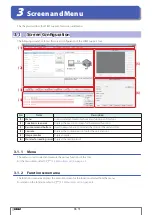
Page 17: ...sic command buttons Used to execute basic commands that control the unit and tool 4 Console Displays the communication log for the unit and tool 5 Image monitor Displays images 6 Monitor for reading result Displays the reading result 3 1 1 Menu The menu is used to select and execute the various functions of this tool For the menu items refer to F 3 2 Menu Items List on page 3 4 3 1 2 Function scre...

Page 18: ...Save WB RAM WB ROM Saves the WB2F current values to the setting values area non volatile memory Load WB ROM WB RAM Loads the setting values in the WB2F setting values area non volatile memory and sets them as the current values Clear Edit data Discards the setting values loaded into the tool Reset Resets the WB2F Initialize Initializes the WB2F 3 1 4 Console This area displays the console screen U...

Page 19: ...Image Saves the displayed image Clear Erases the displayed image Redraw Redraws the displayed image Expand Enlarges the displayed image Full Range Changes the selected rectangular area to be the full area Confirm Range Confirms the selected rectangular area Cancel Range Cancels the selected rectangular area 3 1 6 Monitor for reading result The monitor for reading result displays the reading result...

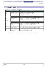
Page 20: ...cking and modifying WB2F settings Tuning Opens the screen for tuning the WB2F Symbol check Opens the screen for checking reading with the WB2F Image manager 1 Opens the screen for managing images saved to the WB2F Generate setting symbol Opens the screen for generating symbols for setting the WB2F Firmware Opens the screen for updating the WB2F firmware Tool Tool settings Modifies the WB2F Support...

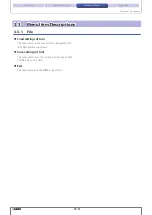
Page 21: ...tem Descriptions 3 3 1 File z z Load settings of tool This menu items loads a saved tool configuration file Only XML files are supported z z Save settings of tool This menu item saves the current tool settings to a file The file extension is XML z z Exit This menu item exits the WB2F Support Tool ...

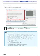
Page 22: ...n settings screen is first displayed 5 1 2 3 4 No Name Function 1 Communication settings Configures communication between the WB2F Support Tool and WB2F 2 PORT search Searches for valid ports on the PC again 3 Default settings Resets the communication settings to the default values 4 Connection start stop Starts and stops the connection between the WB2F and PC 5 Connect automatically Automatically...

Page 23: ...ing bodies The image capture timing for moving bodies can be adjusted by using One Shot Reading ON When One Shot Reading ON is enabled and reading is executed from an external input the image is cap tured one time and decoding is performed regardless of the read settings If an image is captured immediately after reading the initial captured image can be acquired Adjust the reading target so that i...

Page 24: ...data output method 1 2 3 No Name Description 1 Configuration items list You can check and modify the WB2F settings For details on the settings refer to the user s manual 2 Save the WB setting file Saves all WB2F setting values to a CSV file 3 Reflect the WB setting file Applies the content of the CSV file saved in Save the WB setting file 2 to the WB2F WB2F setting value operations are performed i...

Page 25: ... setting values 1 The setting values can be edited in the Configuration items list 1 after they are received 2 Click Send after you have finished editing the setting values The current values are applied to the WB2F 3 Click Save The current values are saved the setting values area non volatile memory If you turn off the WB2F power supply without performing the procedure to transmit the setting val...

Page 26: ...fy automatic tuning and the read parameter table 1 2 3 4 No Name Function 1 Auto tuning Select the tuning target and tuning method and then execute tuning 2 Item You can check and modify the setting values in the read table 3 Custom tuning function You can check and modify the setting values for custom tuning 4 Symbol check buttons You can check symbols ...

Page 27: ...checking reading with the WB2F You can check and modify the setting values in the read table 1 2 3 No Name Function 1 Common settings You can check and modify common setting values in all read tables 2 Table settings You can check and modify the setting values in each read table 3 Symbol check buttons You can check symbols ...

Page 28: ...ve images and delete images This function cannot be used when the WB2F is connected via RS 232 1 2 3 No Name Function 1 Temporary area RAM Performs the temporally image memory area RAM operation 2 Non volatile area ROM Performs the nonvolatile image memory area ROM operation 3 Operation Check Checks operation by executing image capture etc The image can be checked on the image monitor ...

Page 29: ...Generate setting symbol This screen generates symbols for setting the WB2F The WB2F can be set by reading the setting symbols 1 2 No Name Function 1 Preview You can check the generated setting symbols file 2 Generate setting symbol Specify the conditions to generate the setting symbols file ...

Page 30: ...2 firmware update Updates the firmware after the firmware to update is selected Normally clear the Boot loader is running now check box before use Use this check box when a portion of the firmware was unintentionally erased due to a problem such as the power supply being turned off when writing the firmware How to update the firmware Use the following procedure to update the firmware 1 Select the ...

Page 31: ...port Tool 3 3 4 Language z z 日本語 Japanese This menu item changes the WB2F Support Tool display language to Japanese 3 3 5 Help z z Version information This menu item displays the version information The following screenshot shows an example of the Version Information dialog box z z User s Manual This menu items displays the WB2F Support Tool user s manual this manual ...

Page 32: ...nication port is not displayed Is the WB2F correctly connected Check if the computer and the WB2F are correctly connected Has the communication port been recognized in Device Manager Check the communication port that the WB2F is connected to in Device Manager When using a USB connection has the device driver been installed Check that the device driver has been correctly installed When using a RS 2...

Page 33: ...e some time The maximum time About 1 min 30 sec Check the communication settings from maintenance mode 1 Switch to maintenance mode Refer to the WB2F user s manual 2 Start the WB2F Support Tool and click Connection with the default settings Default settings Speed 9600 bps Flow control None Data length 8 Prefix 5E 00 00 00 Parity EVEN Suffix 0D 0A 00 00 Stop bits 1 Check digit None 3 Double click C...

Page 34: ...g value Item Setting value Detailed setting value Speed 07 115200 bps Check digit 00 Disabled Data length 00 7 bit Uppercase response 00 Disabled lowercase Parity 00 NONE Prefix 5e 00 00 00 Stop bits 01 2 bit Suffix 0d 0a 00 00 CR LF Flow control 00 None Check each of the detailed setting values from the setting values by referring to the WB2F user s manual 6 Exit the WB2F Support Tool and then tu...

Page 35: ...3 00010011 DC4 20 14 00010100 NAK 21 15 00010101 SYN 22 16 00010110 ETB 23 17 00010111 CAN 24 18 00011000 EM 25 19 00011001 Character Decimal Hexadeci mal Binary SUB 26 1A 00011010 ESC 27 1B 00011011 FS 28 1C 00011100 GS 29 1D 00011101 RS 30 1E 00011110 US 31 1F 00011111 SP 32 20 00100000 33 21 00100001 34 22 00100010 35 23 00100011 36 24 00100100 37 25 00100101 38 26 00100110 39 27 00100111 40 28...

Page 36: ... 01011001 Z 90 5A 01011010 91 5B 01011011 92 5C 01011100 93 5D 01011101 94 5E 01011110 _ 95 5F 01011111 96 60 01100000 a 97 61 01100001 b 98 62 01100010 Character Decimal Hexadeci mal Binary c 99 63 01100011 d 100 64 01100100 e 101 65 01100101 f 102 66 01100110 g 103 67 01100111 h 104 68 01101000 i 105 69 01101001 j 106 6A 01101010 k 107 6B 01101011 l 108 6C 01101100 m 109 6D 01101101 n 110 6E 011...

Page 37: ...device driver 2 3 L Language 3 15 Load settings of tool 3 5 M Menu 3 1 Menu Item Descriptions 3 5 Menu Items List 3 4 Monitor for reading result 3 3 O Operation Confirmation Method 2 3 Overview 1 1 P Procedures to transmit and receive setting values 3 9 R Reading symbols 2 5 RS 232 connection 2 4 S Save settings of tool 3 5 Screen Configuration 3 1 Setup 2 2 Software End User License Agreement ii ...

Page 38: ... Page Points 1st 2017 5 2nd 2017 11 iv Addition of Version up information 3rd 2018 3 iv Addition of Version up information v Addition of Related manuals 4th 2019 9 All Change to document format Updated screenshots and functions to latest screenshots and functions ...

Page 39: ...19 4th edition 6 64 Nishi Miyahara 2 Chome Yodogawa ku Osaka Japan 2019 IDEC CORPORATION All Rights Reserved C The specifications and content in this manual may be changed without prior notification Reproduction of this manual without prior permission is prohibited All rights reserved ...

Page 40: ... tw idec com Hong Kong IDEC Izumi H K Co Ltd Tel 852 2803 8989 info hk idec com China Shanghai IDEC Shanghai Corporation Tel 86 21 6135 1515 idec cn idec com China Shenzen IDEC Shenzen Corporation Tel 86 755 8356 2977 idec cn idec com China Beijing IDEC Beijing Corporation Tel 86 10 6581 6131 idec cn idec com Japan IDEC Corporation Tel 81 6 6398 2527 marketing idec co jp Specifications and other d...

Page 41: ...B 1956 3 ...

Reviews: