3 Analog I/O Modules
30-16
WindO/I-NV4 User’s Manual
■
Data Type
The analog input value can be handled as the set data type. There are seven data types for the analog inputs.
YES: Supported, NO: Not supported
Optional range
Scales the analog input value to a digital value with 12-bit or 16-bit resolution in the specified minimum and maximum
value range (-32,768 to 32,767) and stores it in the data register.
However, when
PTC Thermistor (threshold)
is selected as
Signal Type
, the range of the minimum and maximum
value is 100 to 10,000.
*1
Binary data (12bit)
and
Optional range (12bit)
are displayed only for FC6A-J8A1 and FC6A-J8A4.
*2 Can only be set when
Signal Type
is thermocouples, resistance thermometers or
NTC Thermistor
.
*3 Resistance when using the FC6A-J8CU1 or FC6A-J8CU4 and
Signal Type
is set to
PTC Thermistor
or
Ohm meter
.
*4
Binary data (16bit)
and
Optional range (16bit)
can be used with the following versions.
FC6A-J8A1, FC6A-J8A4: Hardware version 200 or later (Refer to “ Checking the Hardware Version Number” on page 30-4.)
If an FC6A-J8A1 or FC6A-J8A4 that does not correspond to the above version numbers is set to
Binary data (16bit)
or
Optional range (16bit)
, an error will occur and the module will operate as
Binary data (12bit)
.
Data Type FC6A-J2C1
FC6A-J2C4
FC6A-J4A1
FC6A-J4A4
FC6A-J8A1
FC6A-J8A4
FC6A-J4CN1
FC6A-J4CN4
FC6A-J4CH1Y
FC6A-J4CH4Y
FC6A-J8CU1
FC6A-J8CU4
FC6A-L06A1
FC6A-L06A4
FC6A-L03CN1
FC6A-L03CN4
Binary data
YES
YES
YES
YES
YES
YES
YES
YES
Optional
range
YES
YES
YES
YES
YES
YES
YES
YES
Celsius (℃)
NO
NO
NO
YES
YES
YES
NO
YES
Fahrenheit
(℉)
NO
NO
NO
YES
YES
YES
NO
YES
Resistance
(Ω)
NO
NO
NO
NO
NO
YES
NO
NO
Binary data
(16bit)
NO
NO
YES
NO
NO
NO
NO
NO
Optional
range
(16bit)
NO
NO
YES
NO
NO
NO
NO
NO
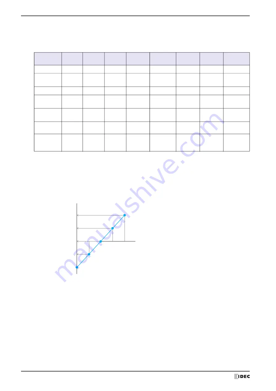
Example: The digital resolution data is 12bit, the range of the input voltage value is -10 to +10V, the minimum is
-1000 and the maximum is 1000.
Input Voltage Value
0
1000
-1000
500
-500
Stored Value
Digital Resolution Data (12bit)
-1024
-5V
-2048
-10V
2047
10V
0
0V
1024
5V
Summary of Contents for WindO/I-NV4
Page 1: ...B 1701 16 User s Manual...
Page 108: ...5 WindO I NV4 Common Operations and Settings 2 76 WindO I NV4 User s Manual...
Page 256: ...7 BACnet Communication 3 148 WindO I NV4 User s Manual...
Page 372: ...6 Screen Restrictions 5 32 WindO I NV4 User s Manual...
Page 390: ...5 Part Library Function 6 18 WindO I NV4 User s Manual...
Page 420: ...3 Text 7 30 WindO I NV4 User s Manual...
Page 628: ...2 Multi State Lamp 9 34 WindO I NV4 User s Manual...
Page 924: ...4 Meter 11 76 WindO I NV4 User s Manual...
Page 990: ...7 Timer 12 66 WindO I NV4 User s Manual...
Page 1030: ...4 Using Data and Detected Alarms 13 40 WindO I NV4 User s Manual...
Page 1098: ...4 Using the Data 15 22 WindO I NV4 User s Manual...
Page 1248: ...5 Restrictions 22 18 WindO I NV4 User s Manual...
Page 1370: ...2 Monitoring on the MICRO I 25 28 WindO I NV4 User s Manual...
Page 1388: ...4 Restrictions 26 18 WindO I NV4 User s Manual...
Page 1546: ...5 Module Configuration Dialog Box 30 36 WindO I NV4 User s Manual...
Page 1614: ...3 Settings 34 14 WindO I NV4 User s Manual...
Page 1726: ...5 Text Alignment A 10 WindO I NV4 User s Manual...


