WindO/I-NV4 User’s Manual
3-59
5 User Communication
3
Co
m
m
un
ica
tio
n
BCC (Block Check Code)
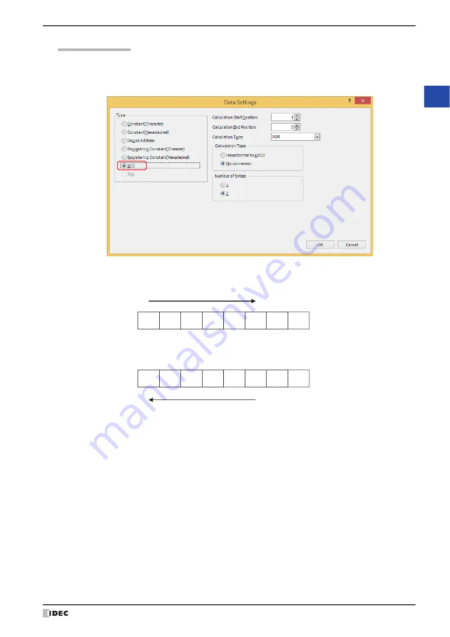
A BCC for the transmission data is automatically calculated and appended to the transmission data at an arbitrary
position and transmitted.
This can be configured only when
TXD
or
Inching
is selected as
Type
on the Command Settings dialog box, and
BCC
is selected under
Type
on the Data Settings dialog box.
■
Calculation Start Position
Specify the position of transmission data at which BCC calculation starts (1 to 15). The position is counted backwards,
with the first position of the transmission data taken as 1.
■
Calculation End Position
Specify the position of transmission data at which BCC calculation ends (0 to 15). The position is counted forwards,
with the data position before the BCC taken as 0.
■
Calculation Type
Select the method to calculate the data between the Calculation Start Position and Calculation End Position.
1
(31h)
4
(34h)
5
(35h)
2
(32h)
STX
(02h)
3
(33h)
BCC
CR
(0Dh)
(1)
(2)
(3)
(4)
(5)
(6)
Calculation Start Position:
Transmission data:
1
(31h)
4
(34h)
5
(35h)
2
(32h)
STX
(02h)
3
(33h)
BCC
CR
(0Dh)
(5)
(4)
(3)
(2)
(1)
(0)
Calculation End Position:
Transmission data:
XOR:
Calculates the data with exclusive logical add.
ADD:
Calculates the data using addition.
ADD (2's Complement): Calculates the data using addition, inverts the bit and adds one.
Modbus ASCII (LCR):
Calculation is performed according to the following procedure. Conversion Type:
Hexadecimal to ASCII, Number of bytes: 2
1. Convert the ASCII characters between Calculation Start Position and Calculation End
Position into 1-byte hexadecimal data for each set of two characters.
Example: 37h, 35h
→
75h
2. Calculate the sum of the data obtained in step 1.
3. Invert the bit of the result of step 2 and add one. (2’s complement)
4. Convert the lower one byte data of the result of step 3 into ASCII characters.
Example: 75h
→
37h, 35h
Summary of Contents for WindO/I-NV4
Page 1: ...B 1701 16 User s Manual...
Page 108: ...5 WindO I NV4 Common Operations and Settings 2 76 WindO I NV4 User s Manual...
Page 256: ...7 BACnet Communication 3 148 WindO I NV4 User s Manual...
Page 372: ...6 Screen Restrictions 5 32 WindO I NV4 User s Manual...
Page 390: ...5 Part Library Function 6 18 WindO I NV4 User s Manual...
Page 420: ...3 Text 7 30 WindO I NV4 User s Manual...
Page 628: ...2 Multi State Lamp 9 34 WindO I NV4 User s Manual...
Page 924: ...4 Meter 11 76 WindO I NV4 User s Manual...
Page 990: ...7 Timer 12 66 WindO I NV4 User s Manual...
Page 1030: ...4 Using Data and Detected Alarms 13 40 WindO I NV4 User s Manual...
Page 1098: ...4 Using the Data 15 22 WindO I NV4 User s Manual...
Page 1248: ...5 Restrictions 22 18 WindO I NV4 User s Manual...
Page 1370: ...2 Monitoring on the MICRO I 25 28 WindO I NV4 User s Manual...
Page 1388: ...4 Restrictions 26 18 WindO I NV4 User s Manual...
Page 1546: ...5 Module Configuration Dialog Box 30 36 WindO I NV4 User s Manual...
Page 1614: ...3 Settings 34 14 WindO I NV4 User s Manual...
Page 1726: ...5 Text Alignment A 10 WindO I NV4 User s Manual...


