WindO/I-NV4 User’s Manual
35-77
5 HG1P
35
M
IC
RO
/I
S
pe
cific
atio
ns
• Reading the State of Function Keys
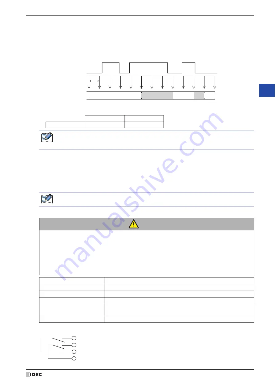
The HG1P reads the state of the function keys once approximately every 20 ms, and those states are applied to the
HMI Expansion Inputs (LI).
When the state of a function key is ON two consecutive times, the HG1P recognizes that the key has been pressed,
and it processes the read result and makes an ON judgment. When the state of a function key is OFF even once, the
HG1P recognizes that the key has been released, and it processes the read result and makes an OFF judgment.
Time to judge the state of the function key
The time from reading the state of the function key to when the result is judged is as follows.
Time to apply the read results to HMI Expansion Inputs (LI)
For function key inputs, the latest read results when the scan for the screen ends are applied to HMI Expansion
Inputs (LI) at that time.
When there is a change in the state of a function key, the time until the read result is applied to the HMI Expansion
Input (LI) is as follows.
Minimum: 21 ms
Maximum: 39 ms + Scan time (HMI Special Data Register LSD4)
Emergency Stop Switch
OFF
→
ON
ON
→
OFF
Maximum
41 ms
20 ms
ON
20 ms
OFF
ON
OFF
OFF
OFF
ON
State of
the function key
Reading the state of the
function key
Read result of the
function key
While executing transmitting and receiving processing for user communications, the time required for the
HG1P to process the read result and make an ON judgment will increase because the read processing for
function keys is executed after communication processing has completed.
The longer it takes for display processing and part processing, the longer it will take to apply the read
results to the HMI Expansion Inputs (LI).
CAUTION
• Use the emergency stop switch through the HG1P optional cable as a control signal for external
devices.
• Consider counter-measures for switch bouncing because bouncing will occur during reset
operation.
• Be careful with the switch. If the switch is subjected to excessive shocks or vibrations, it may
deform or become damaged, chattering may occur, operation may fail, or performance may
become degraded.
Part Number (Manufacturer)
AB6E-3BV02PRM (IDEC)
Number Mounted
1
Contact
2NC (external wiring)
Contact Rating
1A/DC30V
Damage Limits
Mechanical: 100,000 operations minimum
Electrical: 100,000 operations minimum
Reset Operation
Pull or Turn reset
17 (A_NC11)
10 (A_NC21)
18 (A_NC12)
11 (A_NC22)
Removable Connector
Pin Number (Name)
Summary of Contents for WindO/I-NV4
Page 1: ...B 1701 16 User s Manual...
Page 108: ...5 WindO I NV4 Common Operations and Settings 2 76 WindO I NV4 User s Manual...
Page 256: ...7 BACnet Communication 3 148 WindO I NV4 User s Manual...
Page 372: ...6 Screen Restrictions 5 32 WindO I NV4 User s Manual...
Page 390: ...5 Part Library Function 6 18 WindO I NV4 User s Manual...
Page 420: ...3 Text 7 30 WindO I NV4 User s Manual...
Page 628: ...2 Multi State Lamp 9 34 WindO I NV4 User s Manual...
Page 924: ...4 Meter 11 76 WindO I NV4 User s Manual...
Page 990: ...7 Timer 12 66 WindO I NV4 User s Manual...
Page 1030: ...4 Using Data and Detected Alarms 13 40 WindO I NV4 User s Manual...
Page 1098: ...4 Using the Data 15 22 WindO I NV4 User s Manual...
Page 1248: ...5 Restrictions 22 18 WindO I NV4 User s Manual...
Page 1370: ...2 Monitoring on the MICRO I 25 28 WindO I NV4 User s Manual...
Page 1388: ...4 Restrictions 26 18 WindO I NV4 User s Manual...
Page 1546: ...5 Module Configuration Dialog Box 30 36 WindO I NV4 User s Manual...
Page 1614: ...3 Settings 34 14 WindO I NV4 User s Manual...
Page 1726: ...5 Text Alignment A 10 WindO I NV4 User s Manual...


