WindO/I-NV4 User’s Manual
35-79
5 HG1P
35
M
IC
RO
/I
S
pe
cific
atio
ns
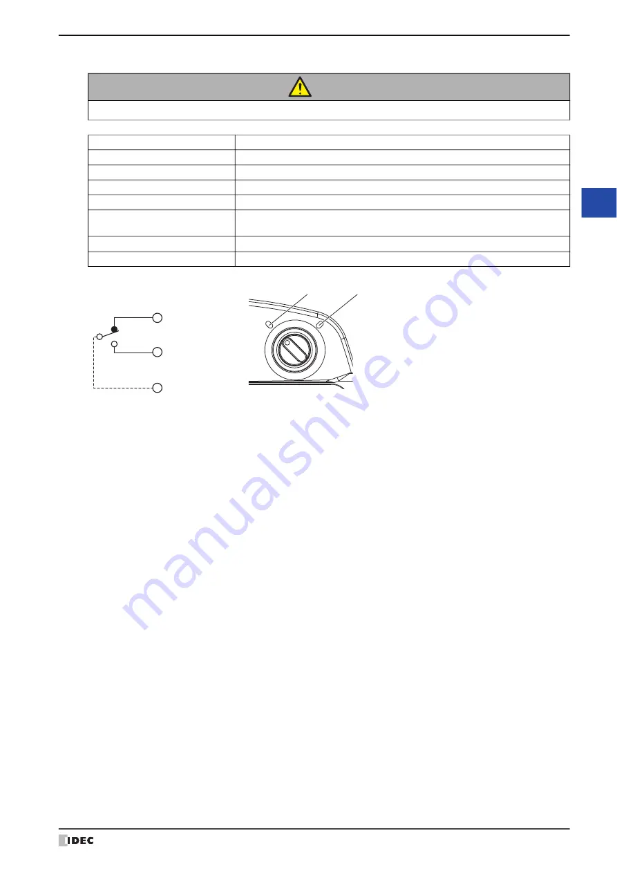
Selector Switch (φ16 or Non-Illuminated model)
When at position (1), pin 1 (C_NC1) and pin 13 (C_C1) are connected.
When at position (2), pin 2 (C_NO1) and pin 13 (C_C1) are connected.
CAUTION
Use the selector switch through the HG1P optional cable as a control signal for external devices.
Part Number (Manufacturer)
LB6S-2T1 (IDEC)
Number Mounted
1
Contact
SPDT (external wiring)
Contact Rating
0.1A/DC30V (resistance load)
LED
Non-Illuminated
Damage Limits
Mechanical: 250,000 operations minimum
Electrical:
100,000 operations minimum
Switching detent
90° - 2-positions
Specification
Stops at all positions (manual)
1 (C_NC1)
2 (C_NO1)
13 (C_C1)
Removable Connector
Pin Number (Name)
(1)
(2)
Summary of Contents for WindO/I-NV4
Page 1: ...B 1701 16 User s Manual...
Page 108: ...5 WindO I NV4 Common Operations and Settings 2 76 WindO I NV4 User s Manual...
Page 256: ...7 BACnet Communication 3 148 WindO I NV4 User s Manual...
Page 372: ...6 Screen Restrictions 5 32 WindO I NV4 User s Manual...
Page 390: ...5 Part Library Function 6 18 WindO I NV4 User s Manual...
Page 420: ...3 Text 7 30 WindO I NV4 User s Manual...
Page 628: ...2 Multi State Lamp 9 34 WindO I NV4 User s Manual...
Page 924: ...4 Meter 11 76 WindO I NV4 User s Manual...
Page 990: ...7 Timer 12 66 WindO I NV4 User s Manual...
Page 1030: ...4 Using Data and Detected Alarms 13 40 WindO I NV4 User s Manual...
Page 1098: ...4 Using the Data 15 22 WindO I NV4 User s Manual...
Page 1248: ...5 Restrictions 22 18 WindO I NV4 User s Manual...
Page 1370: ...2 Monitoring on the MICRO I 25 28 WindO I NV4 User s Manual...
Page 1388: ...4 Restrictions 26 18 WindO I NV4 User s Manual...
Page 1546: ...5 Module Configuration Dialog Box 30 36 WindO I NV4 User s Manual...
Page 1614: ...3 Settings 34 14 WindO I NV4 User s Manual...
Page 1726: ...5 Text Alignment A 10 WindO I NV4 User s Manual...


