3 Operating Modes
1-4
WindO/I-NV4 User’s Manual
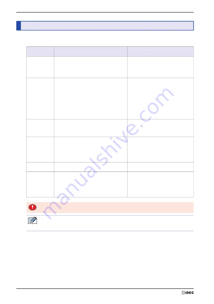
The MICRO/I includes multiple modes, so you switch between modes as and when necessary. These modes are called
operating modes. The functions and the operations and conditions for switching are as follows.
*1 HG2J-7U only
3
Operating Modes
Mode
Functions
Conditions required for
switching to the mode
Run Mode
This is the mode at the time of executing project
data. The created screen is displayed.
• Turn ON the power to the MICRO/I.
• Press [Run] on the Top Page in System
Mode or on the Main Menu.
• The download of the project data is
completed.
System Mode
Perform initial settings, clock settings, self-diagnosis,
etc. for the MICRO/I.
• Press down for 3 seconds or more at the
top-left corner of the screen to display the
Maintenance Screen, and then press
System Mode
.
• Using the screen switching button, multi-
buttons, screen switch or multi commands,
switch to the System Mode.
• All data is cleared using WindO/I-NV4.
• Write the System Area 1 Display screen
number (address 0) to FFFFh.
Monitor Mode
Monitor Mode is used for monitoring values of
device addresses using WindO/I-NV4.
In this mode, the words "Monitor Mode" flashes at
the bottom-left of the MICRO/I screen.
On the WindO/I-NV4
Online
tab, in the
Monitor
group, click
Start Monitor
.
Offline Mode
MICRO/I stops communicating with the external
devices. It takes you to a Main Menu with many
internal settings to choose from including Initial
Setting, Clock Setting and System Information etc.
In this mode, the message "Offline Mode" blinks on
the bottom-left of the MICRO/I screen.
• Press
Offline
on the Top Page in System
Mode or on the Main Menu.
• While monitoring in WindO/I-NV4, on the
Online
tab, in the
Monitors
group, click
Go offline
.
Data Transfer
Mode
Transferring data between a computer and the
MICRO/I.
• Download project data.
• Upload project data.
Boot Mode
Forcibly downloads the MICRO/I OS, system
software and project data if MICRO/I does not start
normally or you forget its password.
• Turn on the power while pressing the RESET
switch on the back of the MICRO/I, and
press and hold the RESET switch for 3
seconds or longer.
• Turn on the MICRO/I with the MICRO/I OS
or system software corrupted.
When switched to System Mode, operation of the MICRO/I stops.
• To display the Maintenance Screen, the
Enable Maintenance
check box from the
System Settings
tab
of the Project Settings dialog box must be checked.
• For details about Maintenance Mode, refer to Chapter 34 “1 Maintenance Screen” on page 34-1.
Summary of Contents for WindO/I-NV4
Page 1: ...B 1701 16 User s Manual...
Page 108: ...5 WindO I NV4 Common Operations and Settings 2 76 WindO I NV4 User s Manual...
Page 256: ...7 BACnet Communication 3 148 WindO I NV4 User s Manual...
Page 372: ...6 Screen Restrictions 5 32 WindO I NV4 User s Manual...
Page 390: ...5 Part Library Function 6 18 WindO I NV4 User s Manual...
Page 420: ...3 Text 7 30 WindO I NV4 User s Manual...
Page 628: ...2 Multi State Lamp 9 34 WindO I NV4 User s Manual...
Page 924: ...4 Meter 11 76 WindO I NV4 User s Manual...
Page 990: ...7 Timer 12 66 WindO I NV4 User s Manual...
Page 1030: ...4 Using Data and Detected Alarms 13 40 WindO I NV4 User s Manual...
Page 1098: ...4 Using the Data 15 22 WindO I NV4 User s Manual...
Page 1248: ...5 Restrictions 22 18 WindO I NV4 User s Manual...
Page 1370: ...2 Monitoring on the MICRO I 25 28 WindO I NV4 User s Manual...
Page 1388: ...4 Restrictions 26 18 WindO I NV4 User s Manual...
Page 1546: ...5 Module Configuration Dialog Box 30 36 WindO I NV4 User s Manual...
Page 1614: ...3 Settings 34 14 WindO I NV4 User s Manual...
Page 1726: ...5 Text Alignment A 10 WindO I NV4 User s Manual...


