WindO/I-NV4 User’s Manual
9-17
2 Multi-State Lamp
9
La
m
ps
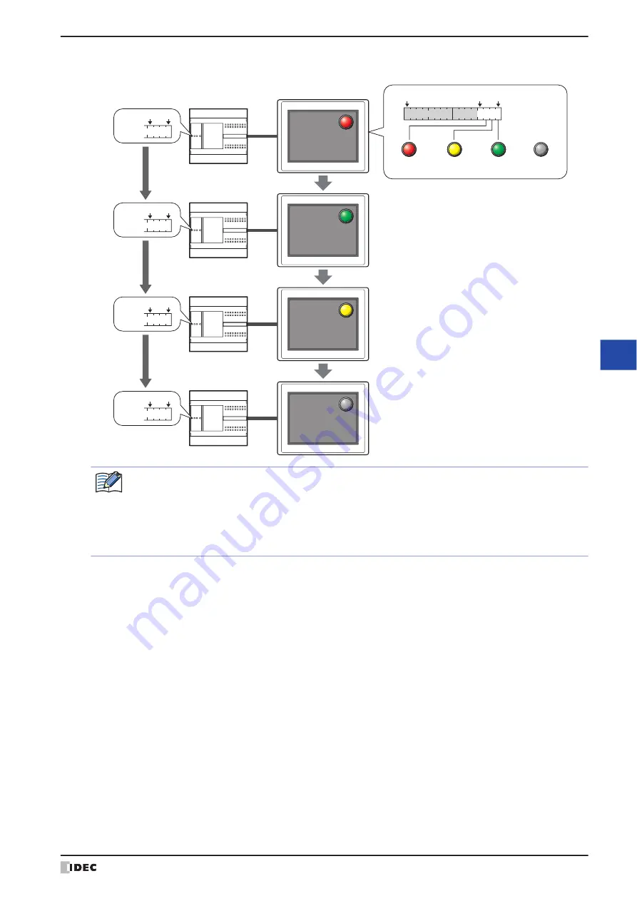
• Display a picture when in the OFF state.
MICRO/I
External device
D0
bit15
bit0
bit3
D0=
0100
bit0
bit3
D0=
0001
bit0
bit3
D0=
0010
bit0
bit3
D0=
0000
bit0
bit3
OFF
State:
0
State:
1
State:
2
The conditions to display the picture set by the OFF state on the screen are as follows.
•
Y
is selected under
Flash
on the
State
tab and the trigger condition is not satisfied.
•
Switching Method
on the
General
tab is
Bit Number
, and the all bit in the device address are 0 or a
bit not allocated a picture is 1.
•
Switching Method
on the
General
tab is
Value
, and the value of device address is a number not
allocated a picture.
Summary of Contents for WindO/I-NV4
Page 1: ...B 1701 16 User s Manual...
Page 108: ...5 WindO I NV4 Common Operations and Settings 2 76 WindO I NV4 User s Manual...
Page 256: ...7 BACnet Communication 3 148 WindO I NV4 User s Manual...
Page 372: ...6 Screen Restrictions 5 32 WindO I NV4 User s Manual...
Page 390: ...5 Part Library Function 6 18 WindO I NV4 User s Manual...
Page 420: ...3 Text 7 30 WindO I NV4 User s Manual...
Page 628: ...2 Multi State Lamp 9 34 WindO I NV4 User s Manual...
Page 924: ...4 Meter 11 76 WindO I NV4 User s Manual...
Page 990: ...7 Timer 12 66 WindO I NV4 User s Manual...
Page 1030: ...4 Using Data and Detected Alarms 13 40 WindO I NV4 User s Manual...
Page 1098: ...4 Using the Data 15 22 WindO I NV4 User s Manual...
Page 1248: ...5 Restrictions 22 18 WindO I NV4 User s Manual...
Page 1370: ...2 Monitoring on the MICRO I 25 28 WindO I NV4 User s Manual...
Page 1388: ...4 Restrictions 26 18 WindO I NV4 User s Manual...
Page 1546: ...5 Module Configuration Dialog Box 30 36 WindO I NV4 User s Manual...
Page 1614: ...3 Settings 34 14 WindO I NV4 User s Manual...
Page 1726: ...5 Text Alignment A 10 WindO I NV4 User s Manual...


