WindO/I-NV4 User’s Manual
12-43
6 Multi-Command
12
Co
m
m
an
ds
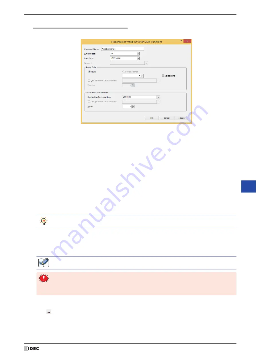
Properties of Word Write for Multi-Functions Dialog Box
Sets the Word Write command for the Multi-Command.
■
Command Name
Enter a name for the command. The maximum number is 20 characters.
■
Action Mode
Select the action to perform when the trigger condition is satisfied from the following:
■
Data Type
Select the data type handled by the operation selected for
Action Mode
.
For details, refer to Chapter 2 “1.1 Available Data” on page 2-1.
UBIN16(W)
and
UBIN32(D)
can only be set if
Action Mode
is set to
OR
,
AND
, or
XOR
.
■
Source 1
Specify the source word device.
Click
to display the Tag Editor. For the device address configuration procedure, refer to Chapter 2 “5.1 Device
Address Settings” on page 2-70.
This setting is enabled only if
Action Mode
is set to
Add
,
Sub
,
Multi
,
Div
,
Mod
,
OR
,
AND
, or
XOR
.
Set:
Writes a fixed value to the specified word device when the trigger condition is satisfied.
Move:
Writes the value in the source device address to the destination word device when the trigger
condition is satisfied.
Set ON & OFF Data:
Writes a fixed value of
ON Data
to the specified word device when the trigger condition is
satisfied.
Writes a fixed value of
OFF Data
to the specified word device when the trigger condition is
no longer satisfied.
Add, Sub, Multi, Div, Mod, OR, AND, XOR: Performs arithmetic on the value of source device address and a fixed
value or a value of device address and writes the result to a word device
when the trigger condition is satisfied.
For details about the
Action Mode
, refer to “Action Mode” on page 12-12. However,
Set ON & OFF Data
for the Multi-Command has the same function as
Momentary
for the Word Write Command.
UBIN16(W)
and
UBIN32(D)
can only be set if
Action Mode
is set to
Move
. Because the number of
device addresses to transfer is specified in Advanced mode, you do not need to set Data Type.
If
BCD4(B)
,
BCD8(EB)
, or
Float32(F)
is selected and the arithmetic data contains a value inexpressible
in BCD, a 1 is written to System Area 2 Processing error bit (address 2, bit 5) and an error
message is displayed. For details, refer to Chapter 4 “Processing error” on page 4-32 and Chapter 36
Summary of Contents for WindO/I-NV4
Page 1: ...B 1701 16 User s Manual...
Page 108: ...5 WindO I NV4 Common Operations and Settings 2 76 WindO I NV4 User s Manual...
Page 256: ...7 BACnet Communication 3 148 WindO I NV4 User s Manual...
Page 372: ...6 Screen Restrictions 5 32 WindO I NV4 User s Manual...
Page 390: ...5 Part Library Function 6 18 WindO I NV4 User s Manual...
Page 420: ...3 Text 7 30 WindO I NV4 User s Manual...
Page 628: ...2 Multi State Lamp 9 34 WindO I NV4 User s Manual...
Page 924: ...4 Meter 11 76 WindO I NV4 User s Manual...
Page 990: ...7 Timer 12 66 WindO I NV4 User s Manual...
Page 1030: ...4 Using Data and Detected Alarms 13 40 WindO I NV4 User s Manual...
Page 1098: ...4 Using the Data 15 22 WindO I NV4 User s Manual...
Page 1248: ...5 Restrictions 22 18 WindO I NV4 User s Manual...
Page 1370: ...2 Monitoring on the MICRO I 25 28 WindO I NV4 User s Manual...
Page 1388: ...4 Restrictions 26 18 WindO I NV4 User s Manual...
Page 1546: ...5 Module Configuration Dialog Box 30 36 WindO I NV4 User s Manual...
Page 1614: ...3 Settings 34 14 WindO I NV4 User s Manual...
Page 1726: ...5 Text Alignment A 10 WindO I NV4 User s Manual...


