WindO/I-NV4 User’s Manual
35-63
4 HG2G-5T, HG1G
35
M
IC
RO
/I
S
pe
cific
atio
ns
4.7 Installation
●
Operating Environment
For designed performance and safety of the HG2G-5T, HG1G, do not install the HG2G-5T, HG1G in the following
environments:
• Where dust, briny air, or iron particles exist.
• Where oil or chemical splashes for long time.
• Where space is filled with oil mist.
• Where direct sunlight falls on the HG2G-5T, HG1G.
• Where strong ultraviolet rays fall on the HG2G-5T, HG1G.
• Where corrosive or combustible gasses exist.
• Where the HG2G-5T, HG1G is subjected to shocks or vibrations.
• Where condensation occurs due to rapid temperature change.
• Where high-voltage or arc-generating equipment (electromagnetic contactors or circuit protectors) exists in the vicinity.
●
Ambient Temperature
• Allow sufficient space for ventilation, and install the equipment away from heat sources.
• Allow at least 100mm between the HG2G-5T, HG1G and walls or other equipment.
• Do not install the HG2G-5T, HG1G where the ambient temperature exceeds the rated operating ambient
temperature range. When mounting the HG2G-5T, HG1G in such locations, provide a forced air-cooling fan or air-
conditioner to keep the ambient temperature within the rated temperature range.
●
HG2G-5T, HG1G Installation
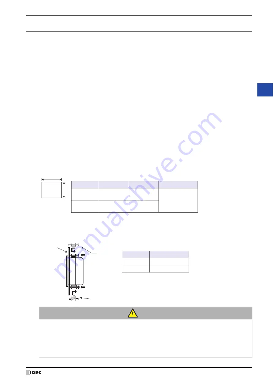
• Make a panel cut-out on the panel with the dimensions shown below.
• Use the attached mounting clips to tighten the screws evenly to mount panel: screws must be applied on total of
four places for HG2G-5T and on total two places for HG1G with the specified torque.
Mounting clips can be attached to the left and right sides of HG2G-5T. However, if they are attached in such way,
there is a risk of not satisfying product specifications such as waterproof performance, shock resistance, and
vibration resistance performance.
CAUTION
• Do not tighten with excessive force, otherwise the HG2G-5T, HG1G may warp and cause wrinkle
on the display, or impair the waterproof characteristics.
• If the mounting clips are tightened obliquely to the panel, the HG2G-5T, HG1G may fall off the panel.
• When installing the HG2G-5T, HG1G into a panel cut-out, make sure that the gasket is not twisted.
Especially when re-installing, take special care because any twists in the gasket will impair the
waterproof characteristics.
Unit: mm
Type No.
A
B
Panel Thickness
HG2G-5T
121.0
+2.0
0
153.0
+2.0
0
1.0 to 5.0
HG1G
92.0
+1.0
0
118.0
+1.0
0
B
A
Mounting Clip
Mounting Clip
Panel
Unit: mm
Type No.
Specified Torque
HG2G-5T
0.2 to 0.3
HG1G
0.3 to 0.35
Summary of Contents for WindO/I-NV4
Page 1: ...B 1701 16 User s Manual...
Page 108: ...5 WindO I NV4 Common Operations and Settings 2 76 WindO I NV4 User s Manual...
Page 256: ...7 BACnet Communication 3 148 WindO I NV4 User s Manual...
Page 372: ...6 Screen Restrictions 5 32 WindO I NV4 User s Manual...
Page 390: ...5 Part Library Function 6 18 WindO I NV4 User s Manual...
Page 420: ...3 Text 7 30 WindO I NV4 User s Manual...
Page 628: ...2 Multi State Lamp 9 34 WindO I NV4 User s Manual...
Page 924: ...4 Meter 11 76 WindO I NV4 User s Manual...
Page 990: ...7 Timer 12 66 WindO I NV4 User s Manual...
Page 1030: ...4 Using Data and Detected Alarms 13 40 WindO I NV4 User s Manual...
Page 1098: ...4 Using the Data 15 22 WindO I NV4 User s Manual...
Page 1248: ...5 Restrictions 22 18 WindO I NV4 User s Manual...
Page 1370: ...2 Monitoring on the MICRO I 25 28 WindO I NV4 User s Manual...
Page 1388: ...4 Restrictions 26 18 WindO I NV4 User s Manual...
Page 1546: ...5 Module Configuration Dialog Box 30 36 WindO I NV4 User s Manual...
Page 1614: ...3 Settings 34 14 WindO I NV4 User s Manual...
Page 1726: ...5 Text Alignment A 10 WindO I NV4 User s Manual...


