5 Key Button
8-82
WindO/I-NV4 User’s Manual
■
View Switching Method
Select how to display the ON/OFF status of the button.
*7 Advanced mode only
Button:
Pressing the button changes the drawing object displayed.
Device Address: The drawing objects assigned to the OFF and ON states are displayed when the value of the device
address is 0 and 1, respectively. Specifies the device address used to switch the drawing object
display.
Click
to display the Tag Editor. For the device address configuration procedure, refer to Chapter 2
“5.1 Device Address Settings” on page 2-70.
No Image:
The button is not displayed on the screen. The button appears as a dashed line frame on the edit
screen. Pressing the corresponding area on the MICRO/I activates the assigned function. If
No
Image
is selected, the settings for
View
and
Registration Text
are disabled.
Selecting
Device Address
in
View Switching Method
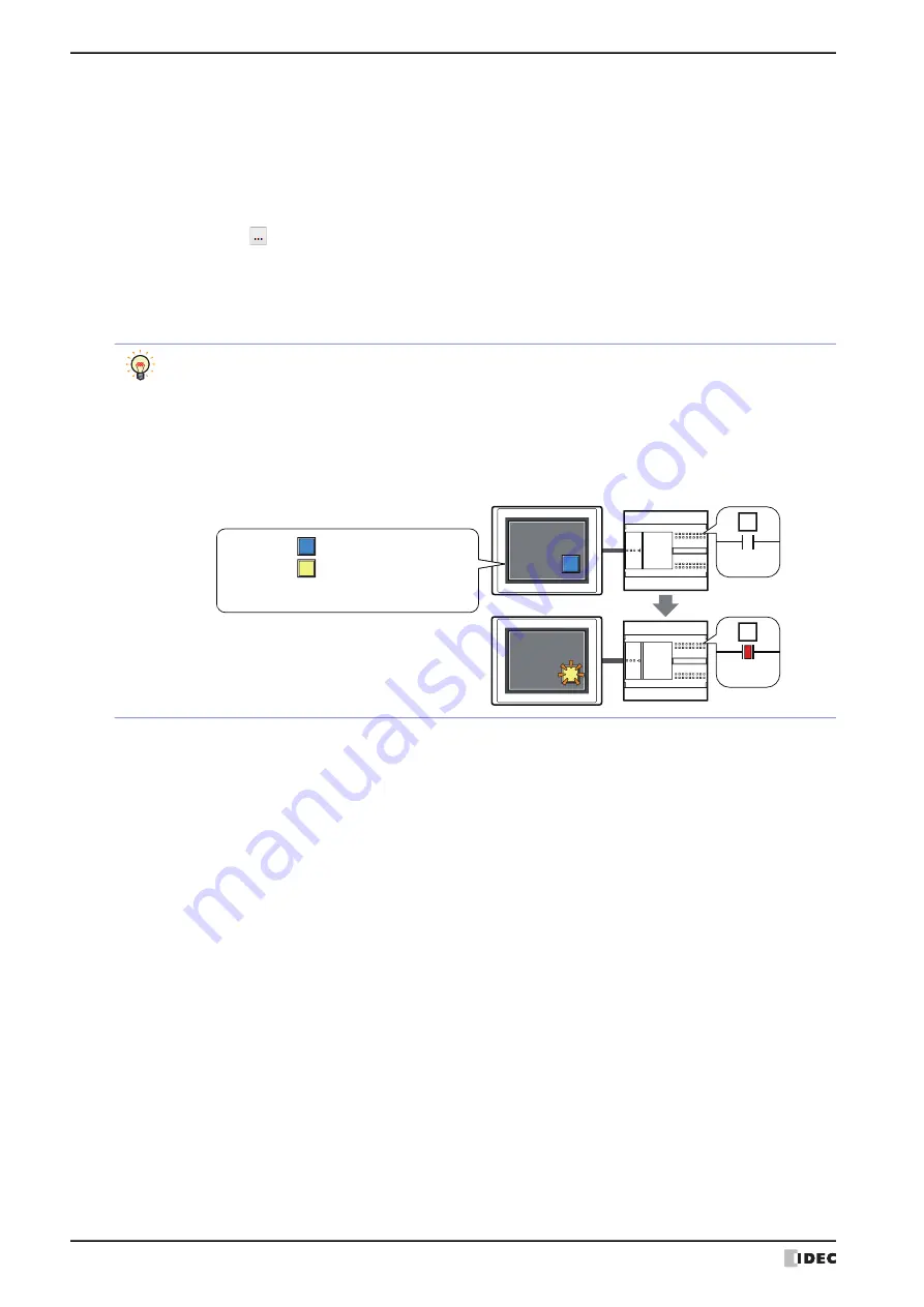
allows you to create an illuminated pushbutton.
The illuminated pushbutton switches state (or image) according to ON or OFF state of the device address,
allowing you to display the state of a device that is being operated.
Example: When you set an external device address 'M0' as
Device Address
in
View Switching Method
,
if the value of M0 changes, the display image will switched according to the value of M0 even if
the button is not pressed.
0
M0
1
M0
MICRO/I
External device
View Switching Method (Device Address): M0
OFF image:
ON image:
Summary of Contents for WindO/I-NV4
Page 1: ...B 1701 16 User s Manual...
Page 108: ...5 WindO I NV4 Common Operations and Settings 2 76 WindO I NV4 User s Manual...
Page 256: ...7 BACnet Communication 3 148 WindO I NV4 User s Manual...
Page 372: ...6 Screen Restrictions 5 32 WindO I NV4 User s Manual...
Page 390: ...5 Part Library Function 6 18 WindO I NV4 User s Manual...
Page 420: ...3 Text 7 30 WindO I NV4 User s Manual...
Page 628: ...2 Multi State Lamp 9 34 WindO I NV4 User s Manual...
Page 924: ...4 Meter 11 76 WindO I NV4 User s Manual...
Page 990: ...7 Timer 12 66 WindO I NV4 User s Manual...
Page 1030: ...4 Using Data and Detected Alarms 13 40 WindO I NV4 User s Manual...
Page 1098: ...4 Using the Data 15 22 WindO I NV4 User s Manual...
Page 1248: ...5 Restrictions 22 18 WindO I NV4 User s Manual...
Page 1370: ...2 Monitoring on the MICRO I 25 28 WindO I NV4 User s Manual...
Page 1388: ...4 Restrictions 26 18 WindO I NV4 User s Manual...
Page 1546: ...5 Module Configuration Dialog Box 30 36 WindO I NV4 User s Manual...
Page 1614: ...3 Settings 34 14 WindO I NV4 User s Manual...
Page 1726: ...5 Text Alignment A 10 WindO I NV4 User s Manual...


