47
MorphoWave Compact - 2018_2000035853
4.5 > Wiegand wiring
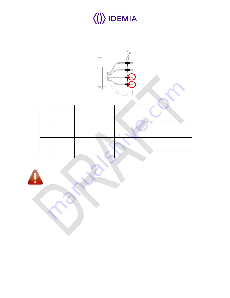
Wiegand input
Figure 14: Wiegand input wiring
21
Green / Red
WIEGAND_IN0
In
Wiegand IN D0
(Output type required: Open drain or
5V+/-5%)
23
White / Red
WIEGAND_IN1
In
Wiegand IN D1
(Output type required: Open drain or
5V+/-5%)
16
Yellow
GPO0
Out
Wiegand LEDIN (typical = 5VDC)
(option)
27
Black / Red
WIEGAND_GND
Ground for Wiegand
If pull-
up’s to 12V have been added on Wiegand IN D0 and Wiegand IN D1 inputs on a
previous installation with a MorphoAccess® 500 Series terminal, these resistors must be
removed to avoid any damage to the
MorphoWave Compact
terminal.
Summary of Contents for MorphoWave Compact
Page 1: ...Copyright 2018 Idemia May 2018 2018_2000035853 MorphoWave Compact Installation guide ...
Page 2: ...Copyright 2018 Idemia May 2018 2018_2000035853 ...
Page 9: ...9 MorphoWave Compact 2018_2000035853 1 Introduction ...
Page 21: ...21 MorphoWave Compact 2018_2000035853 2 General description ...
Page 29: ...29 MorphoWave Compact 2018_2000035853 3 Installation procedure ...
Page 37: ...37 MorphoWave Compact 2018_2000035853 3 3 4 Attach the device on the base plate ...
Page 41: ...41 MorphoWave Compact 2018_2000035853 4 Electrical interface ...
Page 58: ...58 MorphoWave Compact 2018_2000035853 5 User interface ...
Page 64: ...64 MorphoWave Compact 2018_2000035853 6 Accessories Software Licenses and PC Applications ...
Page 67: ...67 MorphoWave Compact 2018_2000035853 7 Recommendations ...
Page 70: ...70 MorphoWave Compact 2018_2000035853 8 Annex 1 finger placement recommendations ...
Page 74: ...74 MorphoWave Compact 2018_2000035853 ...
Page 75: ...75 MorphoWave Compact 2018_2000035853 9 Annex 2 Bibliography ...
Page 78: ...78 MorphoWave Compact 2018_2000035853 10 Annex 3 Support ...
Page 80: ...Copyright 2017 Photo GettyImages 656164914 Copyright 2017 Photo GettyImages 656164914 ...


