background image

i-Q350 RCM 


USER MANUAL 


VISIBILITY DELIVERED. 

PAGE 19 OF 28 

5.  CONNECTING TO THE REEFER CONTROLLER 

Safety Instructions 
A screened cable must be used for the data cable. 
 

Important Note 
The total cable runs between tag and the monitored device must not exceed a total of 15 m. This is due to 
limitations of the RS232 (EIA-232) standard. 
 

Connecting the i-Q350 RCM to the controller 
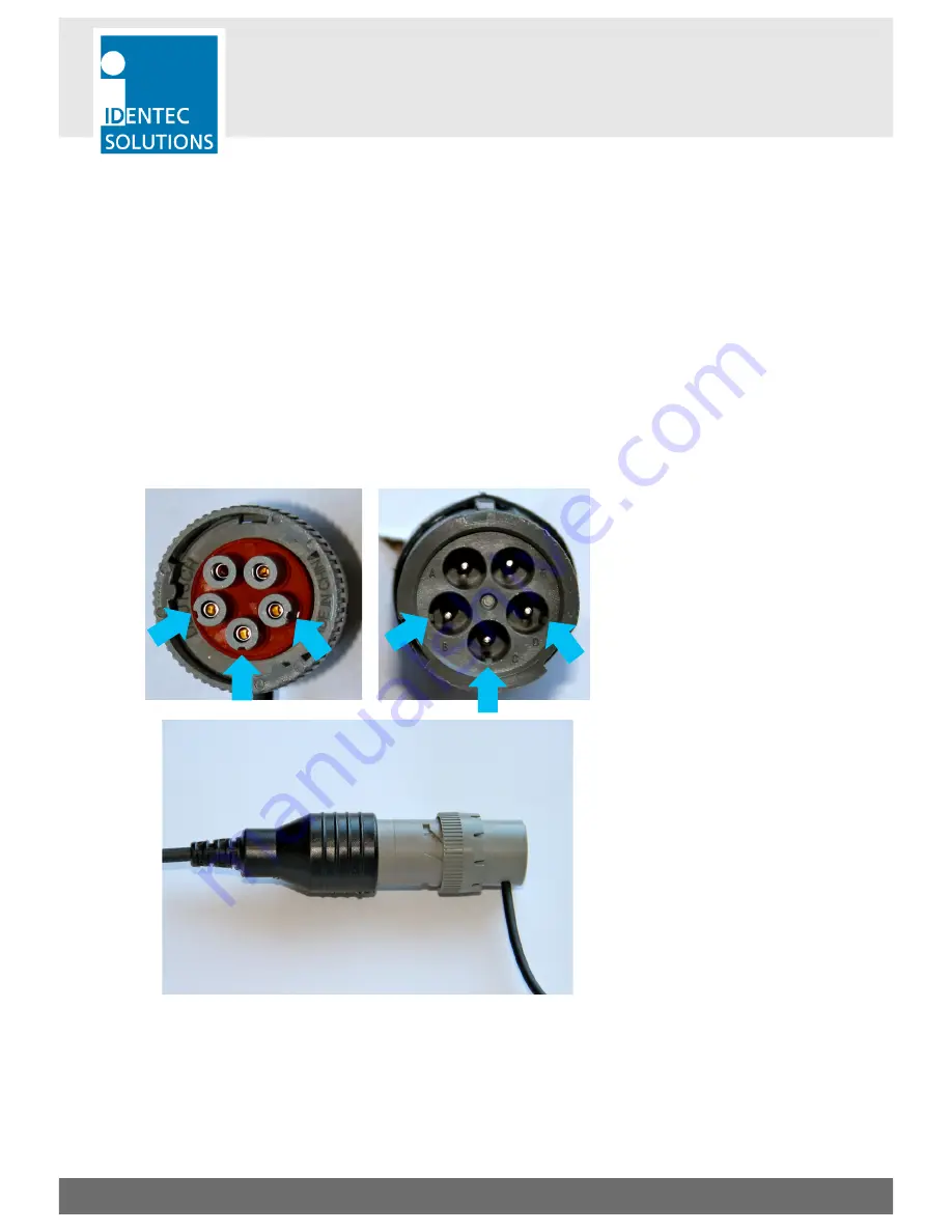
3 of the 5 connector pins are coded with a small edge to align correctly the plug and connector. The 2 
connector pins which are not coded are longer to simplify identification. The data rate of the external device is 
automatically detected. 
Follow the process hereafter to connect the tag to the reefer controller. 


Step 1 
Align the male connector of the i-Q350 
RCM tag to the female connector on 
the reefer connector. 
In order to align correctly the 
connectors, use the indent and edges 
highlighted on the pictures on the left. 


Step 2 
Connect the male connector to the 
female connector. 
Do not apply too much pressure since 
the bayonet locking mechanism might 
not be properly aligned. 


Summary of Contents for i-Q350 RCM SensorSMART

Page 1: ...VISIBILITY DELIVERED i Q350 RCM SensorSMART Installation and Operation Manual...

Page 2: ...sible for proper selection application and use of Products as well as the incorporation integration of Products into other equipment or systems Customer shall indemnify and hold IDENTEC SOLUTIONS harm...

Page 3: ...ollowing standards EN 300 220 1 ETSI EN 300 220 2 ETSI EN 301 489 1 ETSI EN 301 489 3 EN 60950 1 2006 A11 2009 A1 2010 A12 2011 USA Notification This device complies with part 15 of the FCC Rules Oper...

Page 4: ...atic ribbon and earth yourself permanently for the time you handle the unit Avoid unnecessary contact with the unit connectors and assemblies inside the unit Only open the unit if the operational sett...

Page 5: ...NDAMENTALS 10 3 2 SYSTEM COMPONENTS SENSORS 10 3 3 SYSTEM COMPONENTS READERS 12 3 4 SYSTEM COMPONENTS ANTENNAS 12 4 TAG MOUNTING SOLUTIONS 16 4 1 CABLE STRAPS 16 4 2 SCREWS 16 4 3 MAGNET OPTIONAL 18 5...

Page 6: ...ents for Electronic Units of Class 1 Condensate Change of Temperature To avoid condensation in the system the unit must be allowed to slowly adjust itself to warmer temperatures after removal from col...

Page 7: ...f tools Use ESD protected packaging material Never use measuring units with low impedance for measuring or testing systems with semi conductor components Never use high voltage testing units or dielec...

Page 8: ...ll be provided upon request The information in this document may be subjected to changes without prior notice 1 5 Scope of Delivery Visual Inspection Check whether delivery is complete and for any dam...

Page 9: ...lexity out of managing assets personnel safety monitoring and or the tracking of valuable cargo and the need for multiple technologies The unique combination of active RFID RTLS and WSN in one platfor...

Page 10: ...ks directly with the reefer unit s microprocessor controller via the standard external serial port for immediate live monitoring operations The RCM System in conjunction with the i Q350 RCM provides t...

Page 11: ...i Q350 RCM USER MANUAL VISIBILITY DELIVERED PAGE 11 OF 28 Polarization of Sensors 3 2 2 Vertically Polarized Horizontally Polarized Polarization is dependent on orientation and is rotation symmetrical...

Page 12: ...the reader 3 4 System Components Antennas IDENTEC SOLUTIONS antennas are distinguished by their compact design A variety of antennas can be used depending on application The antennas are differentiate...

Page 13: ...as 3 4 2 Because of the smaller apex angle 60 this antenna is more suited to selective data collection and restriction of read zones Depending on the direction of mounting the antenna s field is eithe...

Page 14: ...ILITY DELIVERED PAGE 14 OF 28 Orientation Diagrams Linear polarized antenna Elevation Azimuth Vertical Polarization Horizontal Polarization For this antenna the maximum transmit power setting is W 900...

Page 15: ...R MANUAL VISIBILITY DELIVERED PAGE 15 OF 28 1 Wave Rod Antenna 3 4 3 Overall Dimensions 425 90 mm Mounting proposal Antenna diagram Vertical For this antenna the maximum transmit power setting is Rod...

Page 16: ...ITY DELIVERED PAGE 16 OF 28 4 TAG MOUNTING SOLUTIONS The Tag can be mounted either with cable straps using the 2 slits at each end by using screws or a magnet as described in the following 3 subchapte...

Page 17: ...ld mounting be completed with self tapping screws loosening may occur over time 4 If the tag is mounted outdoors or in a damp environment all mounting parts need to be made of stainless steel or other...

Page 18: ...ELIVERED PAGE 18 OF 28 4 3 Magnet optional The tag can be easily removed by grabbing it on the part of its body with the cable outlet Slightly pull it off the wall and the magnetic holding force is re...

Page 19: ...e to align correctly the plug and connector The 2 connector pins which are not coded are longer to simplify identification The data rate of the external device is automatically detected Follow the pro...

Page 20: ...ERED PAGE 20 OF 28 Step 3 Align the bayonet locking mechanism by rotating the outer ring on the male connector Step 4 Press both connector together and lock the bayonet mechanism to insure proper elec...

Page 21: ...iner s plug s variation we are providing several accessories 6 1 Extension Cable We are providing a 2 meters 6 ft extension cable to accomodate installation where the i Q350 RCM is installed on racks...

Page 22: ...ong and use the standard 5 pin Deustch female connector to connect to the tag Adaptors can be use in combination with extension cable Hereafter are the list of adaptors available for the RCMS solution...

Page 23: ...RCM tag to the female connector of the adaptor or extension cable In order to align correctly the connectors use the indent and edges highlighted on the pictures on the left Step 2 Connect the male co...

Page 24: ...i Q350 RCM USER MANUAL VISIBILITY DELIVERED PAGE 24 OF 28 Step 4 Press both connector together and lock the bayonet mechanism to insure proper electrical connection and weatherproofness...

Page 25: ...gnment between antenna data ratio of task requirements available communication time etc The information about system performance is contained in the relevant datasheets When planning the total system...

Page 26: ...use cleaning products containing chemical additives 8 3 Precautionary Maintenance A regular check of the system is recommended Unstable connections could lead to damage and malfunctions of the system...

Page 27: ...350 Operating Frequency 868 MHz EU or 920 MHz NA Transmit Power 1mW Data Data Retention 10 years without power Write Cycles 100 000 writes Memory Size 10 000 Bytes user definable Identification Code 4...

Page 28: ...om 1m 3ft 3 times DIN IEC 68 2 27 Vibrations 3G 20 sine wave cycles 5 to 150 Hz DIN IEC 68 2 6 5G noise 5 to 1 000 Hz 30 minutes DIN IEC 68 2 64 Standard Certification Europe CE EN 300 220 1 3 EN 301...

Reviews: