CLOUD
47
X
0
F
R
EFERENCE
M
ANUAL
19
4. CLOUD 47x0 F characteristics
4.1.
CLOUD 47x0 F high level architecture
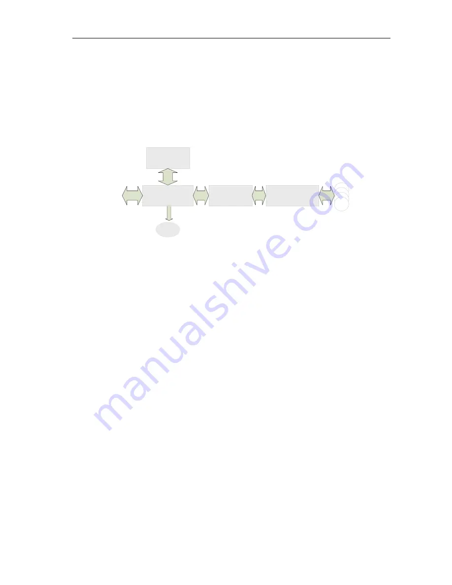
4.1.1. Block diagram
The link between CLOUD 47x0 F and the host to which it is connected is the USB interface
providing both the power and the communication channel.
Device controller
RF front-end
EMC
Matching circuitry
LED
text
text
text
A
n
te
n
n
a
To host
ISO7816 contact
smart card interface
The device controller has several interfaces available. In the CLOUD 47x0 F implementation
three peripherals are connected to the device controller:
LED for reader status indication
A contact smart card interface
An RF front-end that handles the RF communication
The controller embeds flash memory that contains the firmware developed by Identive to
handle all the ISO7816 contact protocol, the RF communication protocols and the PC/SC
communication protocol with the host. The flash can be upgraded once the device is deployed
in the field, hence enabling firmware upgrades to add and potentially patch features.
The RF front-end ensures the coding/decoding/framing modulation/demodulation required for
the RF communication. It is controlled by the device controller through registers.
The matching circuitry provides the transmission and receiver paths adaptation for the antenna
to function properly.


