FD151 Gas Compressor 15
3.3 CRANKCASE OIL PRESSURE
ADJUSTMENT
Your Corken compressor Model FD151 is
equipped with an automatically reversible
geartype oil pump. Ensure that the pumping
system is primed and the oil pressure is properly
adjusted to assure smooth operation.
Before starting your compressor, check and fill the
compressor crankcase with the proper quantity of
lubricating oil.
To assure critical lubrication of crossheads and
crosshead guide during the initial start-up period:
• Remove inspection plate from crosshead guide.
• Fill crankcase with lubricating oil through the
inspection
plate opening (Figure 2.6C).
• Allow the oil to lubricate the crossheads and guide
as it fills into the crankcase.
• Check crankcase oil level at the oil bayonet. (Re-
install the inspection plate and gasket.)
• Follow any other pre-start-up procedures that may
be necessary in your application.
• Double-check the crankcase oil level.
• Start compressor, observing the crankcase oil
pressure gauge. If oil-pressure gauge does not
register 20 - 30 PSIG after 30 seconds, stop the
unit. Refer to Trouble-Shooting Guide in Appendix
J. Consult the Factory if condition cannot be
corrected.
DO NOT continue to run the
compressor without the correct oil pressure.
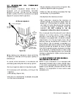
The oil pressure should be about 20 psi (2.4 Bars)
minimum for normal service. If the discharge
pressure is above 200 psi (14.8 Bars) or if the
compressor is equipped with a hydraulic unloader
(Specification 7 or 78; see Figure 3.4A), the oil
pressure must be maintained at a minimum of 25
psi (2.7 Bars). The oil pressure is regulated by a
spring-loaded relief valve mounted on the bearing
housing opposite the flywheel. As shown in Figure
3.3A, turn the adjusting screw clockwise to increase
the oil pressure, counterclockwise to lower it. Be
sure to loosen the adjusting-screw lock nut before
making any adjustments. Tighten locknut back after
any adjustments.
3.4 ADJUSTMENT OF MECHANICAL
UNLOADER CONTROLS
NOTE: If your compressor is not equipped with
mechanical unloader control (valve/ unloader Spec.
7, 78, and 8; see Appendix A to determine if this
applies to your machine), proceed to Section 3.5. See
Section 1.7 for explanation on how suction valve
unloaders work.
Figure 3.3a
Oil Pressure Adjustment
Oil Level Bayonet
Full
Low
Oil
Pressure
Gauge
Oil
Pump
Cover
Lock Nut
Oil Pressure
Adjusting Screw


