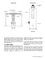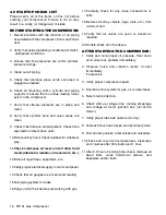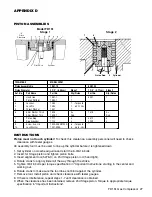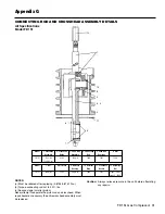
5.3A). Next, remove the roll pin with needle nose
pliers. The castellated nut may now be removed and
the piston platform lifted off the end of the piston rod.
Check the thrust washer and shims for damage and
replace if necessary. (FD151 Stage 1 only). See
Figure 5.4A Below.
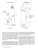
Remove the piston head by using spanner tool Pt. No.
5207-X. Turn piston counterclockwise to remove from
piston rod. Replace piston as noted below. On Model
FD151 (second stage) a roll pin and lock nut are not
used. A small amount of LOCTITE NO. 272 should be
applied to the threads on the piston rod prior to final
assembly of piston. Adjust piston clearance and torque
as noted in Appendix C and D.
Reinstall the piston platform with the same thickness
of shims as before, BUT DO NOT REINSTALL THE
ROLL PIN. Replace the cylinder and install the
piston heads with new piston rings and expanders.
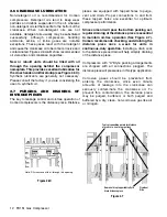
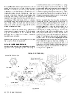
Now measure dimension “X”, shown in the
illustration. If this measurement does not fall within
the tolerances shown in Appendix D, remove the
piston, adjust the shims as necessary and
remeasure the “X” dimension. When the piston is
properly shimmed, tighten the castellated nut, as
shown in Appendix C. Now install a new roll pin to
lock the castellated piston nut in place. Install the
piston head and tighten the socket head bolts in an
alternating sequence. Reinstall the head and follow
standard start-up procedure.
5.5 PISTON ROD PACKING
ADJUSTMENT
Piston-rod packing should be replaced whenever
leakage approaches an unacceptable level.
“Acceptable leakage” should be determined by the
customers according to safety and environmental
regulations for their area. Typically, it is a good idea
to replace piston-rod packing and piston rings at the
same time. Instructions for packing replacement are
included with each set of packing.
Inspection of the rod packing is generally not
productive, since packing that cannot be adjusted to
an “acceptable leakage” rate should be replaced.
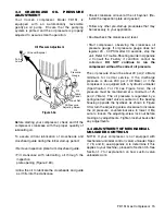
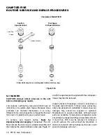
To adjust the packing, remove the compressor
nameplate, tighten the packing-adjusting nut(s) 1/4 turn
with the wrench supplied, then run the compressor a few
minutes to reseat the packing. If the leakage is still
unacceptable, tighten the adjusting nut as necessary,
1/4 turn at a time; do not over tighten! If the adjusting nut
is tightened until the packing spring is solid, the packing
should be replaced. If packing will not seal, carefully
inspect piston rods for possible scoring. Replace if
needed.
Reattach the compressor nameplate after adjustments
or repairs are made.
5.6 BEARING REPLACEMENT
To replace the crankcase roller bearings, wrist-pin
bushing and connecting-rod bearings, begin by
removing the head, cylinder, piston, crosshead guide
and crosshead. Drain the crankcase and remove the
inspection plates. Loosen and remove the
connecting-rod bolts in order to remove the
crosshead/connecting-rod assembly.
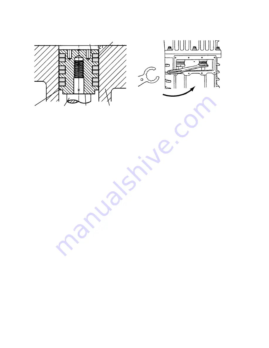
Figure 5.4B
Piston Cross-Section
Model FD151 (Second Stage)
Figure 5.5A
Packing-Adjusting Nuts
Piston Ring
Piston Ring
Expander
Piston Rod
Pistons
Shim Washer
Cylinder
“X” Piston
Clearance
Tighten 1/4 turn


