FD151 Gas Compressor 27
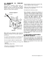
Piston must not touch cylinder!
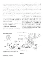
To check this clearance, assembly personnel will need to check
clearance with feeler gauges.
An assembly tool must be used to line up the cylinder before it is tightened down.
1. Set cylinder on crosshead guide and start the 6-3/8-16 bolts.
2. Insert 1st Stage piston and tighten piston bolts.
3. Insert alignment tool (5276-X) on 2nd Stage piston rod (hand tight).
4. Rotate crank to align cylinder all the way through the stroke.
5. Tighten 3/8-16 bolts per torque specification in "Important Instructions: starting in the center and
working out.
6. Rotate crank to make sure the tool does not bind against the cylinder.
7. Remove tool, install piston and check clearance with feeler gauges.
8. If there is interference, repeat steps 1-7 until clearance is obtained.
9. When the clearance has been obtained, remove 2nd Stage piston. Torque to appropriate torque
specification in "Important Instructions".
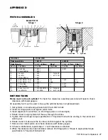
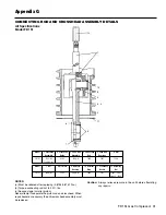
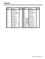
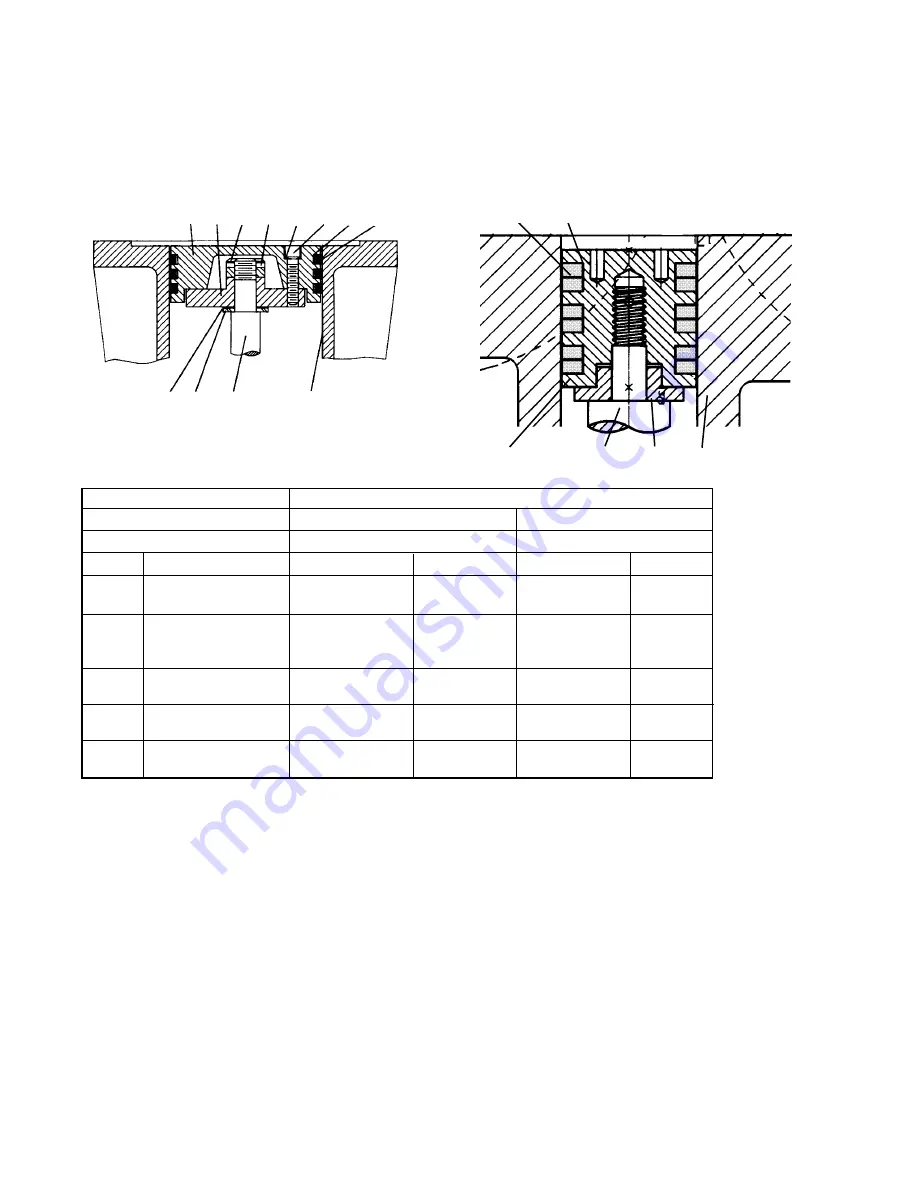
PISTON ASSEMBLIES
Model FD151
Stage 1
Stage 2
TWO-STAGE
MODEL FD151
Piston Assembly No.
1981-1X
5201-XC
Piston Diameter
2-1/2” (6.35 cm)
Stage 1
1-1/4” (3.17 cm)
Stage 2
Ref. No.
Part Name
Part No.
Qty./Piston
Part No.
Qty./Piston
1.
Head, Iron
1981-1
1
5201
1
2.
Piston Platform
1982-1
1
3.
Locknut
1482
1 -Torque to
4.
Lock Pin
1483
1 60 Ft. Lbs.
5.
Thrust Washer
1527
1
6.
Shim Washer, Thick
1528
As
1378
As
Shim Washer, Thin
1528-1
Req.
Req.
7.
Piston Ring
1771
3
3572
3
8.
Ring Expander
1774
3
4209
3
9.
Screw, Sco. Hd.
7002-008 NC125A
6 -Torque to
*
10.
Lock Washer
7207-008A
6 36 In. Lbs.
INSTRUCTIONS
7
8
1 Piston Rod 6 Cylinder
APPENDIX D
1
9
10
4
3
2
7
8
5
6
Piston Rod
Cylinder
“X”
Piston
Clearance


