background image

4 FD151 Gas Compressor

Corken industrial gas compressors are unique
among compressors their size. Unlike ordinary
lubricated gas compressors, Corken compressors
completely isolate the pressurized gas in the
compression chamber from the crankcase. While
piston rings seal the piston tightly enough for it to do
compression work, they do not provide enough
sealing to isolate the compression chamber from the
crankcase. To further seal the compression chamber,
a crosshead/piston rod design with seals around the

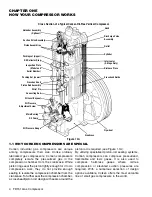
piston rod is required (see Figure 1.1A).
By utilizing specialized piston-rod sealing systems,
Corken compressors can compress pressurized,
flammable and toxic gases. It is also used to
compress harmless gases where oil-free
compression or elevated suction pressures are
required. With a numerous selection of design
options available, Corken offers the most versatile
line of small gas compressors in the world.

1.1 WHY CORKEN COMPRESSORS ARE SPECIAL

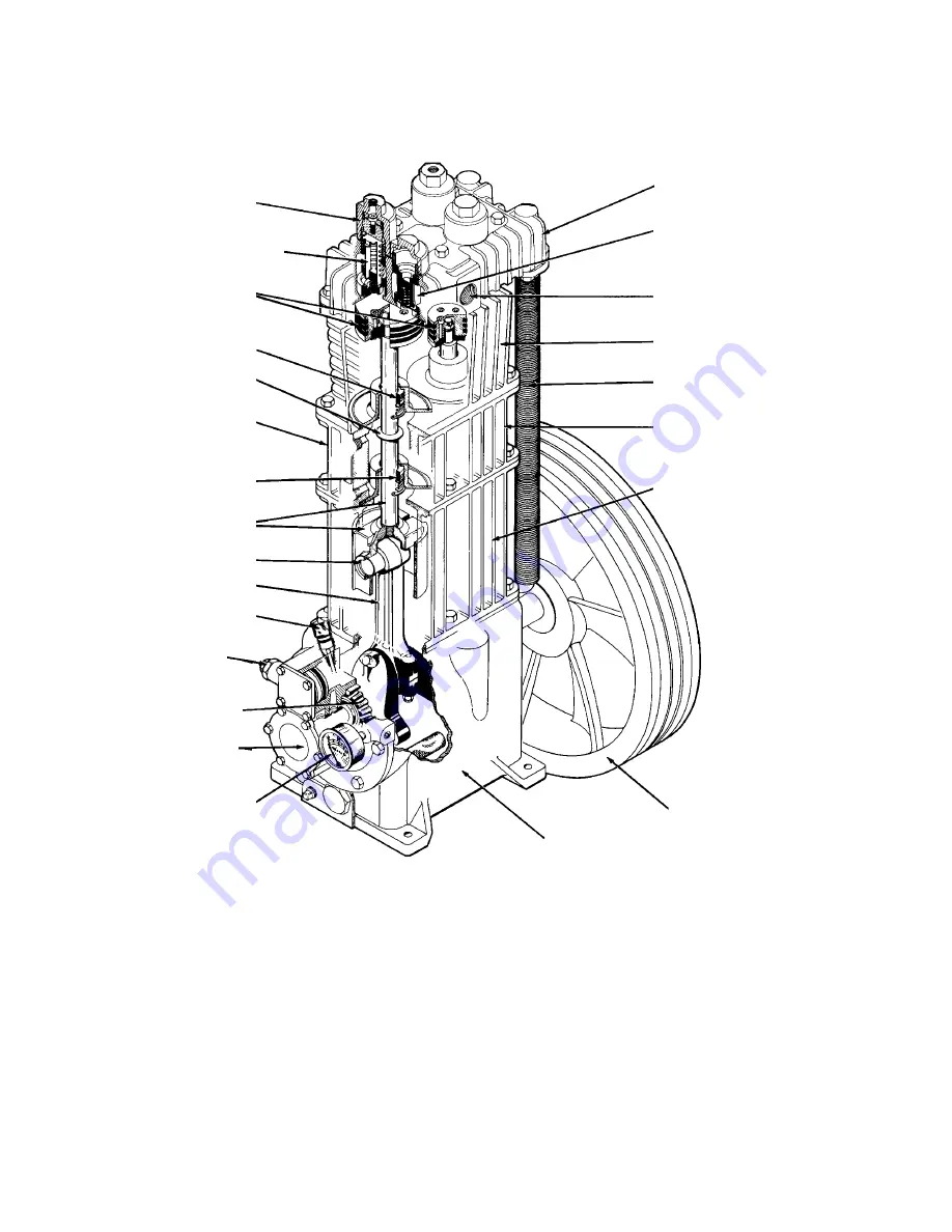
Unloader Assembly

(Optional)

Piston Assemblies

Packing set (Upper)

Suction Valve Assembly

Oil Deflector Ring

Packing Set (Lower)

Wrist Pin

Connecting Rod

Oil Level Bayonet

Main Bearing

Inspection Plate

(Model and 

Serial Number)

Crosshead and

Piston Rod Assembly

Oil Pressure 

Adjustment Screw 

Oil Pump

Oil Pressure Gauge

Head

Discharge Valve
Assembly

Outlet

Cylinder

Intercooler
(2-Stage Only)

Distance Piece

Crosshead Guide

Crankcase

Flywheel

Figure 1.1A

Cross Section of a Typical Corken Oil-Free Vertical Compressor

CHAPTER ONE
HOW YOUR COMPRESSOR WORKS

Summary of Contents for Corken FD151

Page 1: ...of Corken products must comply with Corken instructions applicable laws and safety standards such as NFPA Pamphlet 58 for LP Gas and ANSI K61 1 1972 for Anhydrous Ammonia 4 Transfer of toxic dangerou...

Page 2: ......

Page 3: ...nloader Controls 15 3 5 Startup Check List 16 CHAPTER FOUR ROUTINE MAINTENANCE CHART 17 CHAPTER FIVE ROUTINE SERVICE AND REPAIR PROCEDURES 18 5 1 Valves 18 5 2 Cylinder and Head 19 5 3 Piston Rings an...

Page 4: ...le and toxic gases It is also used to compress harmless gases where oil free compression or elevated suction pressures are required With a numerous selection of design options available Corken offers...

Page 5: ...to the piston Corken s automatically reversible oil pump design allows the machine to function smoothly in either direction of rotation A replaceable 10 micron spin on oil filter ensures long life 1...

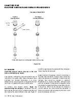
Page 6: ...hat the piston rings seal against the cylinder wall see Figure 1 4A 1 5 VALVES The typical Corken compressor valve consists of a seat bumper spring and valve disk as shown in Figure 1 5A Special heat...

Page 7: ...e disk to hold the suction valve in an open position In this position no compression will occur even though the pistons are still moving up and down The unloaders are controlled by devices which contr...

Page 8: ...be cut in the baseplate for filling the middle section of the channel iron base with grout See additional foundation design aids in appendix H 2 3 PIPING Proper piping design and installation is as i...

Page 9: ...r attempts to compress a non compressible fluid in this situation high impact stresses are created that will result in serious damage to the compressor On applications where the presence of entrained...

Page 10: ...rical float switches If the liquid level should rise too high the level switch will open and disconnect the power to the motor starter stopping the compressor This design ensures the machine will be p...

Page 11: ...an the flywheel A humid climate can cause problems particularly in explosion proof motors The normal breathing of the motor as well as alternating between being warm when running and cool when stopped...

Page 12: ...essors is the distance piece Distance pieces are equipped with tapped holes to purge vent and drain Proper connections to and from these tapped holes are essential for optimum compressor performance S...

Page 13: ...of the compressor first or second stage Otherwise the purge gas will tend to leak into the compression chamber Purging and buffering can be accomplished by venting the distance piece to a safe releas...

Page 14: ...to avoid forcing the belts on Normal rotation is counterclockwise facing the flywheel This is important for two stage units with intercoolers Improper belt tension and sheave alignment can cause vibra...

Page 15: ...fer to Trouble Shooting Guide in Appendix J Consult the Factory if condition cannot be corrected DO NOT continue to run the compressor without the correct oil pressure The oil pressure should be about...

Page 16: ...reservoirs etc 12 Drain all liquid traps separators etc 13 Verify proper electrical supply to motor and panel 14 Check that all gauges are at zero level reading 15 Test piping system for leaks 16 Pur...

Page 17: ...factory for additional recommendations for your specific applications and operating pressures The initial set of piston rings may wear faster than replacement rings Piston ring life tends to get bette...

Page 18: ...ssor Valves may then be removed Inspect valves for breakage corrosion scratches on the valve disk and debris In many cases valves may simply be cleaned and reinstalled If valves show any damage they s...

Page 19: ...re to avoid damage or corrosion to the head and cylinder If the compressor will be left open for more than a few hours coat bare metal surfaces with rust preventative When reassembling the compressor...

Page 20: ...should be replaced whenever leakage approaches an unacceptable level Acceptable leakage should be determined by the customers according to safety and environmental regulations for their area Typically...

Page 21: ...necting rod bearings are easily replaced after removing the semicircular inserts Make sure the indentations in the connecting rod bearing and connecting rod line up when installing the new bearings Be...

Page 22: ...g and replace if necessary Check the oil pump shaft bushing in the bearing carrier If the bushing is corroded pitted or worn the oil pump shaft bushing should be replaced Before reassembling the oil p...

Page 23: ...te for a few minutes while fogging oil into the compressor suction 3 Relieve V belt tension 4 Plug all openings to prevent entry of insects and moisture The cylinders may also be protected with a vapo...

Page 24: ...CROSSHEAD ALL GRAY IRON ASTM A48 CLASS 30 NONE PISTON RINGS FD151 STAGE 1 PTFE GLASS AND MOLY FILLED ALLOY 50 FD151 STAGE 2 PEEK PISTON RING EXPANDERS ALL 302 STAINLESS STEEL NONE HEAD GASKET FD151 H...

Page 25: ...5 1 1 4 3 17 2 5 6 35 2 8 79 5 8 164 Max Allow Rod Min Inlet Pressure Max Pressure Max Motor Max Outlet Model Loads LB Kg psia Bars psia Bars Size Hp Temp F C FD151 3600 1632 96 3 21 1200 83 8 15 350...

Page 26: ...e Conrod Clearance Wrist Cylinder Bore Cylinder Piston Ring FD151 Bearing to Crankshaft Pin to Wrist Pin Diameter Max Finish RMS Radial Thickness Journal Bushing Max Min Stage 1 0 0005 0 0025 0 0009 2...

Page 27: ...arance with feeler gauges 8 If there is interference repeat steps 1 7 until clearance is obtained 9 When the clearance has been obtained remove 2nd Stage piston Torque to appropriate torque specificat...

Page 28: ...on Rod Assembly 1132 X3 Quantity 1 FD151 1132 X4 Quantity 1 FD151 2nd Stage 1452 1X3 Packing Set with 1452 1 1453 1 1454 5 1628 1714 1452 2X3 Packing Set Alloy Optional 4383 X Crosshead Guide Assembly...

Page 29: ...TIFICATION OF VALVE UNLOADER SPEC Example Model No FD151M 4 FBA FD151M 78 FBAB FD151M 9 FBA Valve Unloader Spec APPENDIX F Suction Specification 4 Discharge All Specifications HEAD HEAD Suction Valve...

Page 30: ...ead Gaskets 22 3485 Discharge Valve Seat 23 3486 Discharge Valve Bumper 24 4008 Discharge Spring 25 3973 Discharge Valve Plate 27 3919 X Unloader Assy 28 3919 Unloader Piston 29 2857 Piston Cap 30 261...

Page 31: ...fter replacing 0 8754 0 8751 Dia b Torque connecting rod nut to 30 ft lbs c Second stage smaller piston Never attempt to separate the piston rod and crosshead When repair becomes necessary the entire...

Page 32: ...xample Model No FD151AM 4 FBA Valve Unloader Spec Crankcase Assembly No 2955 X1 M3 4 8 9 2549 X1 Flywheel Assembly Not Shown 16 Optional Flywheel Assembly 3271 X1 Not Shown 14 Caution Always relieve p...

Page 33: ...ng Oil Bayonet 2 112A O Ring Pump Shaft 2 116A O Ring Filter Screen 2 218A O Ring Closure Body 2 Required Spec 3 4 8 9 Only 2 228A O Ring Pump Cover 7001 025 NC050A Bolt 1 4 20 x 1 2 Hex Head 7001 037...

Page 34: ...nn Rod 2 1981 1 Piston Head Iron 1 1982 1 Piston Platform 1 1991 Tube Elbow 3 8T X 2 2 011A O Ring Buna N 1 2 031J O Ring H D Viton 4 2 111A O Ring Buna N 1 2 112A O Ring Buna N 1 2 112A O Ring Buna N...

Page 35: ...383 X Crosshead Guide Assy 1 4395 Packing Cartridge 2 4397 Cartridge Spacer 2 4398 Cartridge Holddown Screw 2 4943 Crankcase Vent Tag 1 5000 125 Retainer Ring 6 5200 Cylinder FD151 1 5201 Piston Head...

Page 36: ...in this area consult Factory TWO STAGE COMPRESSOR TROUBLESHOOTING GENERAL REF POSSIBLE CAUSES SOLUTIONS 1 Valves broken stuck or leaking Inspect and clean or repair 2 Piston ring worn Inspect and rep...

Page 37: ...e Date Time Outside Temperature Hour Meter Readings Stage 1 Stage 2 Suction Pressure Discharge Pressure Suction Temperatures Discharge Temperature Check List Oil Level Belt Tension Change Oil Gauges Z...

Page 38: ......

Page 39: ......

Page 40: ...9201 North I 35 Service Road Oklahoma City OK 73131 Phone 405 946 5576 Fax 405 948 7343 E mail cocsalesdept idexcorp com Web address www corken com Printed in U S A April 1999...

Reviews: