6 FD151 Gas Compressor
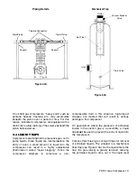
Corken manufactures compressors with one, two,
or three packing sets. Standard-style units contain
one packing set. For completely oil-free
compression, two packing sets are used (see
Figure 1.3A). Oil-free compressors are designated
by the prefix “D". Oil that seeps past the first
packing set is prevented from reaching the second
by an oil deflector ring. Three packing sets and two
distance pieces are available on special machines
for compressing highly corrosive gases. Units with
three packing sets are designated by the prefix "T".
The construction of the "D"- and "T"-style units
ensures that no part of the rod which travels into
the crankcase enters the cylinder.
The distance pieces may be vented or purged with
an inert gas. The orientation of the packing varies
with the application. See Sec. 2.10 and Appendix F
for more details.
1.4 PISTON/PISTON RINGS
Corken compressors use iron pistons that are
locked to the piston rod. The standard piston ring
material is a glass-filled PTFE polymer specially
formulated for non-lubricated service. Piston ring
expanders are placed behind the rings to insure that
the piston rings seal against the cylinder wall (see
Figure 1.4A).
1.5 VALVES
The typical Corken compressor valve consists of a
seat, bumper, spring and valve disk, as shown in
Figure 1.5A. Special heat-treated alloys are utilized
to prolong the life of the valve in punishing non-
lubricated services. The valve opens whenever the
pressure on the seat side exceeds the pressure on
the spring side. The discharge valve is an inverted
version of the suction valve.
1.6 COOLING
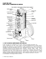
Your Corken compressor model FD151 is air-cooled.
It is important to maintain good air flow around your
compressor. Keep this in mind as you select the
location where the compressor will operate.
1.7 SUCTION VALVE UNLOADERS
(OPTIONAL)
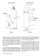
Some Corken compressors are equipped with
suction valve Unloaders. Check your model number
against Appendix A to determine the valve/unloader
Gas Pressure Forces
Ring Against Wall
Piston Ring
Groove
Piston Ring
Expander
Piston Ring
Cylinder Wall
Figure 1.4A
Gas flows down from cylinder
Figure 1.5A
Figure 1.3A
Suction Valve
Spec 4, 7, 78, 8, 9
Discharge
Valve
Suction
Valve Seat
Suction
Valve Plate
Suction
Spring
Suction Valve
Bumper
Discharge
Valve Bumper
Discharge
Valve Spring
Discharge
Valve Plate
Discharge
Valve Seat
Distance Piece (‘D’ Style)
V-Ring
Packing
Deflector
Ring
Packing
Spring
Packing
Adjustment
Nut


