8 FD151 Gas Compressor
2.1 LOCATION
Corken compressors are designed and
manufactured for outdoor duty. For applications in
which the compressor will be subjected to extreme
conditions for extended periods, such as hot boiler
rooms, corrosive environments, arctic or desert
conditions, etc., consult Corken. Check local safety
regulations and building codes to assure installation
will meet local safety standards.
Corken recommends that machines compressing toxic
or flammable gases be placed outdoors. If such units
are placed indoors, make sure the area is well
ventilated. Vent the distance piece to the outdoors or
purge the distance piece with an inert gas and vent to
a safe disposal area.
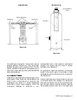
2.2 FOUNDATION
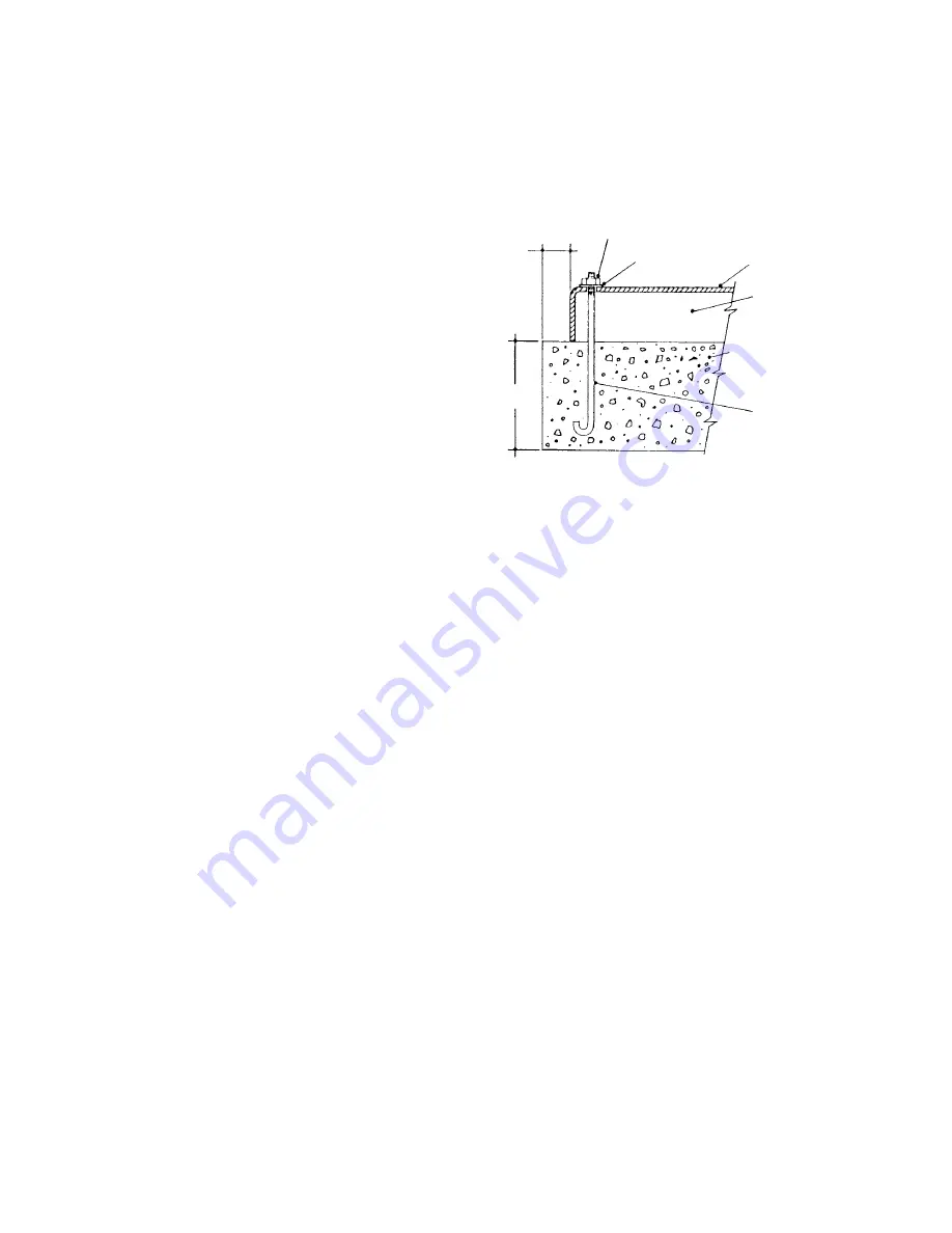
Proper foundations are essential for a smooth running
compression system. Corken recommends the
compressor be attached to a concrete slab at least 8"
thick, with a 2" skirt around the circumference of the
baseplate. The baseplate should be securely
anchored into the foundation by 1/2"diameter "J" bolts
12" long. The total mass of the foundation should be
approximately twice the weight of the compressor
system (compressor, baseplate, motor, etc.). After
leveling and bolting down the baseplate, the volume
beneath the channel must be grouted iron baseplate
to prevent flexing of the top portion of the "J" bolt that
extends beyond the foundation. The grout also
improves the dampening capabilities of the
foundation by creating a solid interface between the
compressor and foundation.
On models mounted on a longer baseplate a hole
can be cut in the baseplate for filling the middle
section of the channel-iron base with grout. See
additional foundation design aids in appendix H.
2.3 PIPING
Proper piping design and installation is as important
as the foundation is for smooth operation of the
compressor. Improper piping installation will result
in undesirable transmission of compressor vibration
to the piping.
DO NOT
SUPPORT
PIPING WITH THE
COMPRESSOR.
Unsupported piping is the most frequent cause of
pipe vibration. The best method to assure
transmission of vibration from the compressor to the
piping is minimized by using flexible connectors (see
Figure 2.3A).
Pipe must be adequately sized to prevent excessive
pressure drop between the suction source and the
compressor, as well as between the compressor and
the final discharge point. In most cases, piping should
be at least the same diameter as the suction nozzle
on the compressor.
Care must be taken if a restriction device such as a
valve, pressure regulator, or back-check valve is to
be installed in the compressor's suction line. The
suction line volume between the restrictive device
and the compressor suction nozzle must be at least
ten times the swept cylinder volume.
Piping must be installed to prevent condensate from
draining into the compressor. This is especially
important on applications where gas is being handled
at or near its saturation point.
Figure 2.2A
2” Min.
All Sides
8” Min.
Hex Nut
Washer
Compressor
Baseplate
Grout Beneath
Base
Concrete Foundation
With Reinforcements
Should be Used on
All Models
1/2” “J” Bolts
12” Long
Recommended Foundation Details
for Corken Compressors
Note:
Locate “J” Bolts Per
Compressor Outline
Dimension Drawings
CHAPTER TWO
INSTALLING YOUR CORKEN COMPRESSOR


