background image

Summary of Contents for ID391H

Page 1: ......

Page 2: ......

Page 3: ...NERATES USES AND CAN RADIATE RADIO FREQUENCY ENERGY AND IF NOT INSTALLED AND USED IN ACCORDANCE WITH THE INSTRUCTION MANUAL MAY CAUSE HARMFUL INTERFERENCE TO RADIO COMMUNICATIONS OPERATION OF THIS EQUIPMENT IN A RESIDENTIAL AREA IS LIKELY TO CAUSE HARMFUL INTERFERENCE IN WHICH CASE USERS WILL BE REQUIRED TO CORRECT THE INTERFERENCE AT THEIR OWN EXPENSE WARNING CHANGES OR MODIFICATIONS NOT EXPRESSL...

Page 4: ...ce this equipment yourself Refer all servicing to qualified service personnel 14 Damage requiring Service Unplug this equipment from the wall outlet and refer servicing to qualified service personnel under the following conditions A When the power supply cord or the plug has been damaged B If liquid is spilled or objects have fallen into the equipment C If the equipment has been exposed to rain or...

Page 5: ...the environment or human health from uncontrolled waste disposal please separate this from other types of wastes and recycle it responsibly to promote the sustainable reuse of material resources Household users should contact either the retailer where they purchased this product or their local government office for details of where and how they can take this item for environmentally safe recycling...

Page 6: ...User s Manual iv ...

Page 7: ...em 10 Set up General 11 Network 12 System alert 14 Time sync 18 OSD 19 Archive 20 System authority 22 Setting Up the Camera 23 Channel status 25 Assign camera 26 Channel 29 Setting Up the Alert 30 Alarm Out 32 User Define Alarm Out 33 NetCam Alarm Out 34 Email 35 Callback 36 Setting Up the Event 38 Motion 41 Object 42 Video Loss 43 Alarm In 44 User Define Alarm In 44 Text In 45 Audio Detection 46 ...

Page 8: ...arch 58 Time Lapse Search 61 SAVING OF RECORDED VIDEO 64 Save As Clip File 64 Clip Player 65 AUDIO PLAYBACK 69 Checking Audio Recording Configuration 69 Playing Recorded Audio 69 External Saving 70 Appendix 1 Network Setup LAN 71 Appendix 2 WebGuard 73 Appendix 3 Text In Query 79 Appendix 4 Connector Pin Outs 81 Appendix 5 Troubleshooting 85 Appendix 6 Specifications 87 ...

Page 9: ...nt detection block Sequence mode available in all screen formats Hardware watchdog timer function Programmable motion detection for each camera input using graphic user interface Various image enhancement functions Remote monitoring playback and control by using a remote program User friendly interface 32 channel alarm input and 32 channel alarm output Network camera alarm and audio association 32...

Page 10: ...wer LED Is lit when the unit is turned on HDD LED Flickers when the unit accesses to the hard disk drive DVD RW Use to export recorded data to the DVD RW media USB Connect USB devices such as a mouse keyboard USB storage device or printer REAR PANEL 16 Channel Model 32 Channel Model ...

Page 11: ... available at the SPOT Multi Channel menu of SmartGuard SD SPOT Multi Channel Display Alarm Out and HD SPOT Multi Channel Display on the left are supported for Channel 1 to Channel 16 and SD SPOT Multi Channel Display Alarm Out and HD SPOT Multi Channel Display on the right are supported for Channel 17 to Channel 32 Only 32 Channel model SD SPOT Sequence Display Connect a spot monitor which suppor...

Page 12: ...on place the inlet at the bottom of the rack and the outlet on top It is strongly recommended that a fan motor is installed at the inlet and the outlet for air circulation and fit a filter at the inlet to screen dust or foreign substances Maintain the temperature inside the rack or surrounding areas between 41 F to 104 F 5 C to 40 C TURNING ON THE DVR Press the power button located on the front pa...

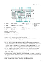
Page 13: ...rd also provides motion detection PTZ control and various image enhancement functions FEATURES Max 32 channels Max 960 images sec recording Reference BNC camera 704 x 480 resolution network camera 1920 x1080 resolution User friendly interface Scheduling by camera and time Time lapse or event driven recording Panic recording Motion detection and object detection function Audio recording PTZ control...

Page 14: ...nt video Clicking the button cancels the adjustment and reloads the original image Audio Out Controls audio out Local Microphone Transmits audio through microphone connected to DVR This is supported for network cameras that support two way audio function Instant Play Allows you to play back video on the camera screen See the Instant Play section p 8 for details PTZ Control Controls PTZ Fit to scre...

Page 15: ...t displays iSCSI screen When setting an iSCSI setup and registering HDD the storage list will be updated Disk Management Clicks the button to format local HDD or to change the settings Clicking disk management displays disk related setup screen When setting is complete the storage list will be updated Storage Info Displays a list of connected storage devices that is available for archiving Set up ...

Page 16: ...ut The user can activate or inactivate alarm out manually by clicking the button when it is released or pressed You can change the alarm out setting values at the ALERT Alarm Out menu of SmartGuard Screen Mode Buttons Click the desired screen mode Double clicking the left mouse button over a camera screen displays video from the camera in the single screen mode and double clicking the left mouse b...

Page 17: ...nd you can control popular PTZ devices and cameras Clicking the PTZ panel button displays the PTZ control buttons as shown below Auto Panning Menu Wiper Pump Light Aux Displays the On Off status of each function Hovering the mouse cursor over any button displays a setup screen and allows you to enable or disable each function and change the advanced settings of the PTZ camera Direction Control Con...

Page 18: ...ser s Manual 10 SmartGuard SETUP Load Loads a saved setting and apply it to the DVR Save Saves the current setting Default Loads the factory default setting and apply it to the DVR Setting Up the System ...

Page 19: ...R continues recording when the hard disk drive is full by overwriting the oldest video Remote Control Serial RS485 RS232 Controls the SmartGuard program with the remote control device connected to the serial COM port Set the connected serial s COM port Device ID Set the remote control device s Device ID Set up COM port Set the COM port s Set the baud rate parity data bit and stop bit Network Contr...

Page 20: ...ces the security of outgoing data from the DVR by using the SSL Secure Sockets Layer protocol when connecting to the DVR remotely When using the SSL function the DVR cannot be connected with a program or a system that does not support the SSL function Selecting Standard does not use the SSL protocol for video and audio data selecting High uses the SSL protocol for all data NOTE The remote setup to...

Page 21: ...ly the DVR s FEN name should be registered on the FEN server and the FEN server settings should match the settings registered on the FEN server Any changes on the FEN server might cause improper operation NOTE The FEN registration is limited to only one FEN server The DVR cannot be registered to multiple FEN servers NOTE When FEN function is enabled it is not necessary to set up port forwarding ma...

Page 22: ...nitor SmartGuard Secondary Monitor SmartSearch Secondary Live Screen 3 Main Monitor SmartGuard SmartSearch Secondary Monitor Secondary Live Screen Extended Spot Following main screen Displays the main screen of SmartGuard identically User configuration Sets the user specific configuration layout sequence Use spot OSD Displays OSD Monitoring Without Login Displays video even while you are logged ou...

Page 23: ...ng each function causes the system alert as follows S M A R T tab Set up alert S M A R T Log Causes the system alert when S M A R T log occurs This is supported only when the installed hard disk drives support S M A R T Self Monitoring Analysis and Reporting Technology Monitoring program Internal hard disk drives only ...

Page 24: ...the threshold temperature of hard disk drives The DVR leaves S M A R T log when the temperature of hard disk drives exceeds the defined threshold Stop recording tab No recording during specified time Causes the system alert when panic recording has been stopped by clicking the panic recording button or when recording has not been made during the predefined time Login Fail 3 times tab Causes the sy...

Page 25: ...dure and enter the ID and password for login Clicking the Add button adds the sender to the sender address book Recipient address book Enter the email address Clicking the Add button adds the recipient to the recipient address book Callback Sends a message to predefined callback servers when system alert occurs Select a callback server from the drop down menu below the Set up button If any callbac...

Page 26: ... conditions Check the time server and network conditions first Run as a server Runs the DVR as a time server As a client Synchronizes the time between a DVR and a time server when they are networked Server Enter the IP address or domain name of target time server Check Time Server Tests the synchronization with the time server Automatic Synchronizes the time automatically at the predefined interva...

Page 27: ...ra Description Displays a camera name which is set at the Location setting of the CAMERA menu State Displays the recording schedule event detection recording status and PTZ on or off Hover Menu Displays the hover menu Time Displays the recorded time of playback video Text In Displays text in data from a POS Elevator Status Displays the elevator status from the outside Event Enables or disables eve...

Page 28: ...ck the Set up button and set up the storage for archiving Enabling Overwrite makes the DVR continue recording when the hard disk drive is full by overwriting the oldest video Disabling Overwrite makes the DVR stop recording when the hard disk drive is full Storage List Displays a list of connected storage devices that is available for archiving Drive Displays a name of the device NOTE It supports ...

Page 29: ...ed to all devices in Storage List Total Storage Displays the total number of storages allocated and to be allocated to all devices in Storage List Create Resize Clicking the button creates or adds storage depending on the number of storages to be allocated in the selected device Format Clicking the button deletes archived video saved in the selected device Remove Clicking the button deletes all st...

Page 30: ...lly when there is no keyboard or mouse operation during the predefined dwell time below Remote connection timeout Clicking each authority level Manager User 1 to 3 displays the Remote connection timeout screen and then you can set the DVR s connection time settings from remote locales Timeout It is allowed to connect during remote connection period you set After time to keep connection the remote ...

Page 31: ... the camera will be recorded while in the record mode PTZ Setup Click the Set up button if the camera is a PTZ camera Device ID Set the device ID number using the slide bar COM port Select the COM port to use When using the RS232 port select COM 1 When using the RS485 port select the given COM port number To check the given COM port number please refer to the installed card information displayed o...

Page 32: ...here you want to start the line Hold down the left mouse button and drag the cursor to where you want the end of the line Release the mouse button and a group of boxes appears along the line you drew You can drawlines around shapes by repeating this process Rectangle Hold down the left mouse button and drag the cursor in any direction A rectangle appears Once the rectangle is the size you want rel...

Page 33: ...Digital Video Recorder 25 Hybrid Model Channel status It displays camera information such as IP address video input type etc ...

Page 34: ...e Displays a camera name set in the camera Model Displays a camera model name IP address Displays a camera s IP address Maximum resolution Displays the maximum resolution of a camera Version Displays the camera firmware version Move Allows you to change the camera number by selecting a camera from the list and clicking the button Remove Remove All Cancels the registration of the selected camera by...

Page 35: ...e camera may not be made properly depending on changes in the external network environment IP Address Searches for a camera with a camera s IP address Enter the IP address and port number in the IP address range and Port fields It is possible to search more than one camera at a time by entering a range of IP addresses It is recommended that the camera not be networked via DHCP Dynamic Host Configu...

Page 36: ...tor group of the camera Selecting Apply to all devices applies the same user ID and password to all selected cameras if you selected more than one camera and the selected cameras have the same user ID and password Firmware Upgrade It allows you to upgrade the firmware of the network camera This is supported for the hybrid model only After selecting an upgrade package select Start to upgrade the ca...

Page 37: ...camera Set up the transmission resolution for remote and RTSP The following two ways are available for setting up the transmission resolution Multistream Automatically transmits the appropriate stream for remote resolution Selecting from Lowest resolution Highest resolution Streams Selecting from the lowest highest resolution automatically transmits the stream corresponding to the lowest or highes...

Page 38: ...User s Manual 30 Setting Up the Alert Non Hybrid Model ...

Page 39: ...Digital Video Recorder 31 Hybrid Model ...

Page 40: ...el only From To Set alarm out activation period Alarm out is activated during the period only If the From time is later than the To time the alarm out will be not activated From end time to time to start time to If you set To 08 00 and From 18 00 this means the alarm will be not activated at the from 8 am to 6 pm and be activated at all other times Dwell time Set the alarm out duration Use audible...

Page 41: ... connected to the DVR via TCP networking Click the Test connections button to test the connection to the device From To Set user define alarm out activation period Alarm out is activated during the period only If the From time is later than the To time the user define alarm out will be not activated From end time to time to start time to If you set To 08 00 and From 18 00 this means the alarm will...

Page 42: ...m To Set alarm out activation period Alarm out is activated during the period only If the From time is later than the To time the alarm out will be not activated From end time to time to start time to If you set To 08 00 and From 18 00 this means the alarm will be not activated at the from 8 am to 6 pm and be activated at all other times Dwell Time Set the alarm out activation duration Alarm out a...

Page 43: ...e SMTP server uses the type of encrypted connection Check the Login box if you want to connect to the SMTP server that requires login procedure and enter the ID and password for login Clicking the Add button adds the sender to the sender address book Recipient address book Enter the email address Clicking the Add button adds the recipient to the recipient address book ...

Page 44: ...User s Manual 36 Callback You can set up callback address book Server address Enter the IP address of the callback server and click the Add button ...

Page 45: ...Digital Video Recorder 37 Push You can set up push server Server address Enter the IP address of the push server ...

Page 46: ...User s Manual 38 Setting Up the Event Non Hybrid Model ...

Page 47: ...detected event is notified by log channel association or action association and the same type of other events detected during the dwell time will not be notified Channel association Records video from multiple cameras when an event occurs at the selected camera or other device ...

Page 48: ...User s Manual 40 Action association Displays actions to be done when an event occurs Clicking the Set up button allows you to change the settings Non Hybrid Model Hybrid Model ...

Page 49: ... channels that an event occurs during the dwell time on the monitoring screen Move to preset Clicking the Set up button displays the list of saved Preset and you can select a Preset The PTZ camera moves to the position of the selected Preset when an event occurs You can save Preset in the PTZ control panel of SmartGuard This function is supported for the camera that supports the PTZ function Alarm...

Page 50: ...ed blocks within the selected detection zone The minimum number of blocks Min size should not exceed the selected block numbers for detection When selecting multiple detection area groups the minimum number of blocks Min size should not exceed the block numbers of the smallest detection area Max size Set the maximum number of blocks no less than the Min size block If you set the Max size value to ...

Page 51: ...ize should not exceed the block numbers of the smallest detection area Max size Set the maximum number of blocks no less than the Min size block If you set the Max size value to 100 the DVR will ignore the changes which are detected in more than 100 blocks Activation times Set the dwell time to detect changes The DVR will detect the change only when the change lasts over the preset dwell time Refe...

Page 52: ...in Description Enter an alarm in device name Alarm in type Enter a signal type of the alarm in device If the signal type of the alarm in device is NC Normally Closed select Normally open If the signal type is NO Normally Open select Normally closed User Define Alarm In You can set up user define alarm in event Enable all Click Enable all to select all of the camera numbers 1 to 32 Displays network...

Page 53: ...ny text string is entered Transaction End Enter the transaction end text string The DVR considers that a transaction ends when the end text string is entered Enter the number of additional text lines to be displayed after the end of the transaction in the More Lines option Line Delimiter Enter the character s that the text in product uses to indicate the end of a line Special characters can be cre...

Page 54: ...all of the camera numbers 1 to 32 Displays the camera number Clicking each button allows you to set up the alarm in event in the DVR for each network camera or buttons are supported for 32 Channel model only Enable Enables the netcam alarm in event function When the network camera detects a netcam alarm in event the DVR also considers it as an event Tampering You can use the tampering event of the...

Page 55: ...amera or buttons are supported for 32 Channel model only Enable Enables the tripzone event function When the network camera detects a tripzone event the DVR also considers it as an event Setting Up the Schedule If a BNC camera is selected clicking Apply all applies the settings to all BNC cameras identically If a network camera is selected clicking Apply all applies the settings to all network cam...

Page 56: ...User s Manual 48 Recording Setup You can set up recording for each camera BNC Cameras ...

Page 57: ...isk drive Resolution Sets the record image size not supported for network cameras Higher resolution images require more storage space and will reduce the recording capacity of the hard disk drive Profile Select one of the preset profiles supported for network cameras only Higher resolution frame rate and quality of the stream assigned to the profile require more storage space and will reduce the r...

Page 58: ... menu IPS See the explanation of Time lapse recording not supported for network cameras Resolution See the explanation of Time lapse recording not supported for network cameras Quality See the explanation of Time lapse recording not supported for network cameras Dwell time Sets the duration of recording The DVR records video for the duration from the time an event is detected Profile Select one of...

Page 59: ...s alarm in event recording User Define Alarm In Enables user define alarm in event recording Text In Enables text in event recording Audio Detection Enables audio detection event recording NetCam Alarm In Enables NetCam alarm in event recording Tampering Enables tampering event recording Tripzone Enables tripzone event recording All Events Enables all events recording Work hour After hour Enable o...

Page 60: ...educes the image size to fit images within the monitor screen size when the image size is bigger than the monitor screen size and some parts of the image is cropped Monitoring Without Login Displays video even while you are logged out Assign channel Monitors the video by arranging cameras manually at the desired location of the monitoring screen Click the camera button and drag the desired locatio...

Page 61: ...he monitors Spot Sequence Set the sequence order on each monitor Spot operation Hold spot during single screen mode Video is not sequenced while the screen mode of SmartGuard is set to the single screen mode Include event display Displays event detected image in the single screen mode when an event occurs Show video loss Displays video of the camera that video loss event is detected Monitoring Wit...

Page 62: ...el Select the authority level Only the administrator level user can edit the user s information and their authority setup The authority setup of the Administrator cannot be edited Delete user Deletes the selected user from the user list Only the administrator level user can delete the user Authority Set the authority of the selected user Apply all users in same level Clicking the button applies th...

Page 63: ...enu button and SmartSearch menu of SmartGuard to get into the SmartSearch mode To return to the SmartGuard mode click the Menu button and SmartGuard menu of SmartSearch FEATURES Searches by camera and time Provides recording status table Various search functions Zoom in out function Print function Remote playback function Bookmark function Saves to video file Audio playback NOTE The play speed is ...

Page 64: ...is on you can control Pan Tilt and Zoom by clicking the left right mouse button The Main PiP is selected as a default Panoramic Panoramic 180 Panoramic 180 2 Selects the panoramic Mode Main PIP Displays PiP Picture in Picture view to select the area easily in the main view screen ePTZ Controls Pan Tilt and Zoom function Dragging the mouse the size of dragging indicates the speed of PTZ The left bu...

Page 65: ...gging it to the desired position on the jog shuttle and holding it plays video at a constant speed Releasing the mouse button causes the icon to return to the center position Clicking the Play button plays video at normal speed Clicking the Shuttle Lock button and dragging and dropping the icon to a desired position fixes the icon in that position Playback Buttons Controls playback of recorded vid...

Page 66: ...or event logs from the first day of this week From one day ago Searches motions or event logs from one day ago One day Searches motions or event logs for one day Find Searches all event results within established find conditions and then displaythem in the result list box below Result Displays the search result Save Image Saves the current image of the result as an image file such as bitmap Privac...

Page 67: ...he area with boxes Clicking outside the area will fill the outer area with boxes If no shapes have been drawn the entire screen will fill with boxes Find Method Select either Change or Object Change Detects changes at the user defined motion detection zone between two consecutive images which are usually motion For example if you want to detect if anyone passes through a door you can draw a Change...

Page 68: ...dition displays the list of recorded video which are associated with the selected text in device Channel Select a text in device number Case Sensitive Distinguishes between capital letter and small letters entered in the Name box Name Enter the text to find Comp Enter the comparison operator Value Enter the comparison value NOTE The tab and line can be used for more specific search of the text in ...

Page 69: ...m In tab and then a device number in the Channel buttons below Clicking the Find button after setting up the search condition displays the list of recorded video which are associated with the selected user define alarm in device Channel Select a user define alarm in device number Time Lapse Search The timetable Go To button calendar and bookmark allows you to search for recorded video on the time ...

Page 70: ...dicates the current playback location of video on the timetable Clicking the mouse on the desired time displays the first image recorded within the time Yellow separation line Separates segments when time overlap occurs In this case the recorded data in the time range located after the separation line is the latest Go To Search Clicking the Go To button displays the following screen Enter the date...

Page 71: ...f the specifictime in the future Clicking the button allows you to bookmark the current playback time and clicking the button deletes the bookmark Clicking a bookmark and hovering the mouse cursor over the bookmark displays the bookmark information camera number time etc Clicking the or button moves to the previous or next list ...

Page 72: ...save recorded video when the user has an authority for External Save The External Save option should be selected at the USER menu NOTE The video file can be saved only under the C IDR Series temp directory or on the removable disk including CD RW DVD RW and USB storage NOTE If you save video in C it must have 5GB or more free space excluding the video file size For example it must have 8GB or more...

Page 73: ...d to install any special software on your personal computer to play back saved video The file contains a Player program Double clicking the target file starts the Player program Clicking on the top right corner of the Player prgram displays the image in the full screen Clicking exits the Player program NOTE It is suggested that the computer used for the Player program has at least an 800MHz Pentiu...

Page 74: ...Playback Buttons Plays back the current video on the screen Goes to the beginning of the video clip Plays the video clip in fast reverse Goes back one frame of the video clip Plays the video clip Goes forward one frame of the video clip Plays the video clip in fast forward Goes to the end of the video clip Cycles through the screen modes It cycles through 2x2 1 7 3x3 4x4 4x5 5x5 and 1 32 NOTE 4x5 ...

Page 75: ...bc_02 exe and abc_03 exe when it is saved you don t need to play each file one by one manually abc_01 exe abc_02 exe and abc_03 exe files will be played successively when you play the abc_01 exe file Move to Previous File Moves the previous file from the currently playing file or the file to be played when playing a split file Move to Next File Moves the next file from the currently playing file o...

Page 76: ... Screen might not display properly If this happens press the ESC key on your PC keyboard to return to the normal screen mode Click the slider bar and move it left or right to move through the video clip Placing the mouse cursor on an image and clicking will cause that image to display full frame ...

Page 77: ...ording Setup tab 3 Check that Record Audio is enabled for each camera Playing Recorded Audio 1 Selecting a camera screen in the playback screen displays the button beside the camera title 2 Clicking the button displays the camera screen menu 3 Click the Audio Playback button 1x1 screen format only NOTE Audio of one camera at a time is played back ...

Page 78: ...bling Quick Erase deletes previously saved files more quickly Eject When Finished Ejects the CD DVD automatically after completing burning or erasing Erase Disc Deletes all data on the CD DVD Burn Starts burning the selected files and folders on the CD DVD NOTE The burning might not be successful if the remaining space of the disk is not enough when saving the new data subsequently after adding fi...

Page 79: ...TCP IP Properties Select Obtain an IP address automatically or Use the following IP address depending on your network environment When selecting Obtain an IP address automatically the DNS server address is set up automatically When selecting Use the following IP address enter the IP address Subnet mask Default gateway and DNS server address acquired from your network administrator ...

Page 80: ...e Use FEN function in the Network Service setting and click the Set up button Name Enter the DVR s name to be registered on the FEN server Click the Name Check button to check if the name you entered can be used Clicking the OK button registers the name as a FEN name of the DVR NOTE The FEN function allows you to connect to the DVR from remote sites using either the dynamic IP addresses or the dom...

Page 81: ...es not work with Microsoft Windows 8 metro UI Select between the LIVE PORT Web live and PLAY PORT Web search modes Enter ID and PASSWORD and click the LOGIN button You will need to enter the DVR IP address in the DVR ADDRESS field when running the IDIS Web program by entering http web idisglobal com Selecting the Use FEN Service option allows you to enter the DVR name registered on the FEN server ...

Page 82: ...on Then enter netsh int tcp set global autotuninglevel disable and press the enter key Restart your computer to apply the changes If you want to enable the Auto Tuning capability again enter netsh int tcp set global autotuninglevel normal after running the Command Prompt with elevated administrator permissions Restart your computer to apply the changes Web Monitoring Mode A remote web monitoring p...

Page 83: ...and click the button again stop monitoring live audio Clicking both button and button allows two way communication Clicking the button disables audio communication Aspect Ratio Changes the image aspect ratio Fit to Screen Fit the video to the size of the camera screen Fit to Aspect Ratio Resizes camera screen to original aspect ratio of the video Half Size x0 5 4 Times Bigger x4 Displays the camer...

Page 84: ...e desired mode Click to print the current video screen using a printer connected to the computer Click to save the video recording as an executable file Click to save the current video screen as an image file Click to configure rendering mode and OSD settings Select rendering mode to adjust the video output rate or select which OSD elements to display on the screen from the OSD list Click to switc...

Page 85: ...you wish to search and then jump to a specific point in the recording 20 Click Reload to reload recent video recordings from remote locales 21 Indicates the selected camera s recording data on a time bar If the camera s system clock has been changed to a point in the past and more than one recording exists at the same point in time as a result you will be able to choose which segment to search fro...

Page 86: ...User s Manual 78 ...

Page 87: ...t tabs can be set Query Example I 1 2 3 4 5 6 123456789012345678901234567890123456789012345678901234567890 Item Unit price Qty amount Coke 2 20 1 s 2 20 Fanta 2 20 1 s 2 20 Hotdog 3 50 3 s 10 50 Pepsi 1 95 1 s 1 95 total 16 85 Thank you In the above text in data you can find that the comparison value is located at 17th Unit price mark will be ignored automatically 28th Qty and 40th amount characte...

Page 88: ... mark will be ignored automatically 28th Qty and 40th amount characters including spaces from the left but the value of amount category is located at the different line from Item In this case you can enter 17 28 and 40 in each Tab size box and enter the tab symbol and line symbol in the Value box for Unit price for Qty and for amount for the next line For example if you want to search for Coke wit...

Page 89: ... 16 S16 Sensor 16 G G Ground G G Ground 32 Channel Model No Connector No Connector 1 S1 Sensor 1 17 S17 Sensor 17 2 S2 Sensor 2 18 S18 Sensor 18 3 S3 Sensor 3 19 S19 Sensor 19 4 S4 Sensor 4 20 S20 Sensor 20 5 S5 Sensor 5 21 S21 Sensor 21 6 S6 Sensor 6 22 S22 Sensor 22 7 S7 Sensor 7 23 S23 Sensor 23 8 S8 Sensor 8 24 S24 Sensor 24 9 S9 Sensor 9 25 S25 Sensor 25 10 S10 Sensor 10 26 S26 Sensor 26 11 S...

Page 90: ...ut 2 2 AOUT3 Alarm Out 3 15 AOUT4 Alarm Out 4 3 AOUT5 Alarm Out 5 16 AOUT6 Alarm Out 6 4 AOUT7 Alarm Out 7 17 AOUT8 Alarm Out 8 5 GND Ground 18 GND Ground 6 AOUT9 Alarm Out 9 19 AOUT10 Alarm Out 10 7 AOUT11 Alarm Out 11 20 AOUT12 Alarm Out 12 8 AOUT13 Alarm Out 13 21 AOUT14 Alarm Out 14 9 AOUT15 Alarm Out 15 22 AOUT16 Alarm Out 16 10 GND Ground 23 GND Ground 11 DO NOT CONNECT 24 DO NOT CONNECT 12 ...

Page 91: ...d 11 DO NOT CONNECT 24 DO NOT CONNECT 12 DO NOT CONNECT 25 DO NOT CONNECT 13 GND Ground No Connector No Connector 1 AOUT1 Alarm Out 17 14 AOUT2 Alarm Out 18 2 AOUT3 Alarm Out 19 15 AOUT4 Alarm Out 20 3 AOUT5 Alarm Out 21 16 AOUT6 Alarm Out 22 4 AOUT7 Alarm Out 23 17 AOUT8 Alarm Out 24 5 GND Ground 18 GND Ground 6 AOUT9 Alarm Out 25 19 AOUT10 Alarm Out 26 7 AOUT11 Alarm Out 27 20 AOUT12 Alarm Out 2...

Page 92: ...User s Manual 84 ...

Page 93: ...d Ask your dealer or distributor Problem The logo appears and then freezes Sometimes the screen is black Solution There is a problem with the Main Board Reboot the DVR If it happens often call your dealer or installer Problem The USB serial converter has been connected to the DVR for the POS installation however the dialog box asking the device driver appears Solution When connecting the POS devic...

Page 94: ...User s Manual 86 ...

Page 95: ...rm out max 16 channels for network cameras of hybrid model only Network alarm out max 16 channels for non hybrid model only Audio Input 16 line in 1 Vp p Network camera audio in max 16 channels for network cameras of hybrid model only Audio Output One line Network camera audio out max 16 channels for network cameras of hybrid model only CONNECTORS Video Input Composite 16 BNC Network camera max 16...

Page 96: ...sions W x H x D 23 2 x 13 7 x 27 6 590mm x 350mm x 700mm Operating Temperature 41 F to 104 F 5 C to 40 C Operating Humidity 0 to 90 Power AC 100 240V 50 60 Hz 3 0 1 5A Approvals FCC CE CB ULiii iii CAUTION Risk of Explosion if Battery is replaced by an Incorrect Type Dispose of Used Batteries According to the Instructions This equipment is indoor use and all the communication wiring are limited to...

Page 97: ...nels for network cameras of hybrid model only Network alarm out max 16 channels for non hybrid model only Audio Input 32 line in 1 Vp p Network camera audio in max 32 channels for network cameras of hybrid model only Audio Output One line Network camera audio out max 32 channels for network cameras of hybrid model only CONNECTORS Video Input Composite 32 BNC Network camera max 32 channels Hybrid m...

Page 98: ...mensions W x H x D 23 2 x 13 7 x 27 6 590mm x 350mm x 700mm Operating Temperature 41 F to 104 F 5 C to 40 C Operating Humidity 0 to 90 Power AC 100 240V 50 60 Hz 3 0 1 5A Approvals FCC CE CB ULiii iii CAUTION Risk of Explosion if Battery is replaced by an Incorrect Type Dispose of Used Batteries According to the Instructions This equipment is indoor use and all the communication wiring are limited...

Reviews: