background image

Part 1 – Introduction

11

 -

I (In)

: Connect an alarm-in device to this port. 

(Mechanism: Choose between an NC (Normally 
Closed) type or an NO (Normally Open) type) 


Connect a mechanical or electrical switch to the 
alarm in port and the GND (ground) connector. 
Alarm in range is 0V to 5V. In order to detect alarm 
input from an electrical switch, the signal must be 
higher than 4.3V from an NC switch or less than 
0.3V from an NO switch and must last for longer 
than 0.5 seconds.


Install Bracket Assembly Hole

Secures the body on the bracket.


NPT 3/4" Cover

Remove the cover to combine the NPT 3/2" pipe.


Heater

Has a built-in heater that enables normal operation in 
sub-zero temperature conditions.


Check your local laws and regulations on making 
video or audio recordings. The user will be held 
liable for any violation of the law.


When switching over from 12 VDC to PoE as the 
power source, the system will be rebooted once the 
power adapter is disconnected.


Organize the power cable so that it will not cause 
people to trip over or become damaged from chairs, 
cabinets, desks, and other objects in the vicinity. Do 
not run the power cable underneath carpet or a rug 
or plug the cable into a power outlet shared by a 
number of other devices.

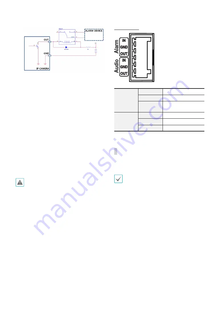
I/O Connector 

Alarm

In

Alarm In

GND

Grounding

Out

Alarm Out (Active Low - 
Open Collector Output)

Audio

In

Audio In

GND

Grounding

Out

Audio Out

Factory Reset

Only use the factory reset switch to restore the camera 
to its factory default settings.

A factory reset will clear all camera settings configured 
by the user.

Shut off the power supply.

Remove the dome cover and then press and hold 
the reset switch down.

Hold the switch down and reconnect the power 
adapter.

Once the device turns back on, wait 5 seconds, and 
then release the reset switch.

The device will go through the resetting process and 
reboot. All camera settings will be restored to their 
factory defaults after the reboot. 

Summary of Contents for LightMaster DC-D Series

Page 1: ...Powered by DC D Series Installation Manual DC D3233HRXL DC D6233HRXL...

Page 2: ...h explanation about some functions may not be incorporated The manufacturer is not responsible for any problems resulting from the use thereof The information contained herein is subject to change wit...

Page 3: ...le system This will prevent damage to the equipment due to lightning and power line surges If thunder or lightning is common where the equipment is installed use a surge protection device 10 Overloadi...

Page 4: ...or human health from uncontrolled waste disposal please separate this from other types of wastes and recycle it responsibly to promote the sustainable reuse of material resources Household users shou...

Page 5: ...Reset 11 Lens 12 Installation 12 Removing the Dome Cover 12 Inserting a SD Memory Card 13 Installation 13 Closing the Dome Cover 14 Angle Adjustment 15 Dimension 15 Part 2 Camera Connection 16 With Di...

Page 6: ...configurations without a PC Supports ONVIF protocol Core specification version 2 4 0 Profile S Multi streaming for high resolution and high quality video monitoring and simultaneous recording in real...

Page 7: ...cameras Multiple event detection modes Backup storage on a microSD memory card as a safeguard against data loss during network interruptions Supports 12 VDC and PoE Power over Ethernet Includes a mot...

Page 8: ...rchasing the product check inside the box to make sure all the following accessories are included Network Camera Terminal Blocks 2 ea Quick Guide CVBS Cable Allen Wrench Screws Anchors each 3 ea Desic...

Page 9: ...otator 5 Lens 6 Dome Cover Assembly Part 7 Bottom Cover 8 Power 9 Network Port 0 Cable Rubber Video Out Factory Reset Switch SD Memory Card Slot Alarm I O Audio I O Install Bracket Assembly Hole NPT 3...

Page 10: ...se ports for previewing video and not monitoring video Go to Remote Setup System General and choose a video out signal NTSC or PAL When removing the cable hold and slightly pull the jack connected to...

Page 11: ...e power source the system will be rebooted once the power adapter is disconnected Organize the power cable so that it will not cause people to trip over or become damaged from chairs cabinets desks an...

Page 12: ...s Motorized focus and zoom lens When installing or handling the camera be careful not to give an impact on the lens to prevent a malfunction from occurring Installation Installation of this product do...

Page 13: ...a shaded area If the camera is installed in direct sunlight it may be affected adversely 1 Use the screws anchor provided with the camera to secure the install bracket on a wall or a ceiling Use the p...

Page 14: ...or the bottom cover clockwise using the allen wrench provided with the camera 6 Connect external devices the network cable and the power adapter 7 Adjust the angle For more information refer to the An...

Page 15: ...s Rotation Used to adjust the lens rotation angle Turn the lens rotator clockwise or counterclockwise direction Vertical Rotation Used to adjust the lens vertical angle Horizontal Rotation Used to adj...

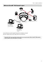
Page 16: ...Out Alarm Out Sensor In Audio In DirectIP NVR makes it easy to use cameras without extra network configurations Each camera can be controlled via the DirectIP NVR setup menu without any PC For detail...

Page 17: ...te Compact microSD Memory Card Alarm Out Sensor In Audio Out Audio In Control the camera over the network from software installed on a computer Ideal for using the camera over the network from a remot...

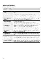
Page 18: ...h Make sure the lens is in focus Adjust the focus during daytime If there is too much light coming into the camera or the camera is picking up an overly bright light source adjust the camera s positio...

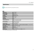
Page 19: ...rol P Iris Angular Field of View Wide 91 5 H 48 4 V 109 D Tele 43 4 H 24 2 V 49 9 D Min Illumination COLOR 0 01 lux F1 2 B W 0 lux IR LED ON Dynamic Range 120 dB True WDR Electronic Shutter Speed Auto...

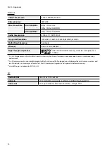
Page 20: ...rd class 6 or higher max 128GB An SLC Single Level Cell or MLC Multi Level Cell card by SanDisk or Transcend is recommended to ensure stable recording performance An SD memory card is a consumable pro...

Page 21: ...40 C 60 C 40 F 140 F Boot Up Temperature 20 C 60 C 4 F 140 F Operating Humidity 0 90 Power Source 12V PoE IEEE 802 3af Class3 Power Consumption 12V 0 97A 11 6W PoE IEEE 802 3af Class 3 Approval FCC C...

Page 22: ...IDIS Co Ltd For more information please visit at www idisglobal com...

Reviews: