background image

FDX-32 User

’s Guide 

76 

8.12  Setting other functions [OTHERS] 

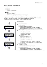
8.12.1  Grouping keys for key lock [KEY LOCK] 


Using menu 

OTHERS → KEY LOCK 


Set value 

MENU KEY LOCK               : Keys of 

  are locked. [Default] 

MENU KEY UNLOCK         : Keys of 

  are not locked. 

CH KEY LOCK                     : Keys of 

  are locked. [Default] 

CH KEY UNLOCK               : Keys of 

  are not locked. 

PRESET LOCK                   : Keys of 

  are locked. [Default] 

PRESET UNLOCK              : 

  are not locked. 

See:  7.5  Setting/Releasing  key  lock


When all keys of 

, and 


are locked, the “ESC” key also will be locked until it is released. 

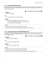
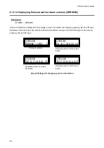
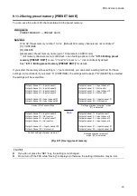
[Fig. 8.13] Grouping for key lock 


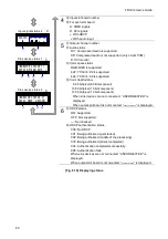
8.12.2  Beep sound [BUZZER] 


Using menu 

OTHERS → BUZZER 


Set value 

ON: Beep sound ON    [Default] 

OFF: Beep sound OFF   


SET

OUTPUT

ALL

INPUT

OFF

9

8

7

6

5

4

0

3

2

1

LOAD

PRESET

MENU

/SET

ESC

V&A

VIDEO

AUDIO

SWITCHING MODE

Menu operation keys

I/O channel setting keys
Switching mode key

Preset memory loading keys
Summary of Contents for FDX-32

Page 1: ...TX RX TX RX TX RX TX B C D OPTICAL OPTICAL OPTICAL OPTICAL DVI D HDMI DVI D HDMI DVI D HDMI DVI D HDMI A B C D DVI D HDMI DVI D HDMI DVI D HDMI DVI D HDMI A B C D DVI D HDMI DVI D HDMI DVI D HDMI DVI...

Page 2: ...ited States and other countries ETHERNET is a registered trademark of Fuji Xerox Corporation Mozilla Firefox and its logo are trademarks or registered trademarks of the Mozilla Foundation in the Unite...

Page 3: ...struction manual may cause harmful interference to radio communications Operation of this equipment in a residential area is likely to cause harmful interference in which case the user will be require...

Page 4: ...if the warning is ignored or the equipment is handled incorrectly Indicates the presence of a hazard that may cause minor personal injury or property damage if the caution is ignored or the equipment...

Page 5: ...Set the power plug in a convenient place to unplug easily You can easily unplug in case of any extraordinary failure or abnormal situation and it also helps for unplugging when you do not use it for a...

Page 6: ...e vent holes If ventilation slots are blocked it may cause fire or failure due to internal heat Do not put heavy items on the product It may fall turn over and lead to injury Do not exceed ratings of...

Page 7: ...the internal parts and result in malfunctions Caution If you lift the FDX with your knees straight fully your back may be damaged When lifting the FDX please bend your knees and get close to the machi...

Page 8: ...8 2 1 Displaying current I O channel status CHANNEL DISPLAY 37 8 3 Setting input INPUT SETTING 38 8 3 1 INPUT EQUALIZER 38 8 3 2 No signal input monitoring time INPUT SIGNAL CHECK 39 8 3 3 HDCP input...

Page 9: ...PCM 65 8 8 7 AC 3 Dolby Digital Audio EDID AC 3 Dolby D 65 8 8 8 AAC Audio EDID AAC 66 8 8 9 Dolby Digital Plus Audio EDID Dolby D 66 8 8 10 DTS Audio EDID DTS 67 8 8 11 DTS HD Audio EDID DTS HD 67 8...

Page 10: ...12 10 Displaying cooling fan status FAN STATUS 82 8 12 11 Displaying supply voltage status POWER STATUS 83 8 12 12 Displaying firmware and hardware versions VERSION 84 9 WEB browser 85 10 Specificatio...

Page 11: ...s are missing or damaged please contact IDK FDX 32 main unit x 1 Terminal block 2 pin x 1 Power cable 1 8m 5 9 feet x1 Rack mounting bracket x 2 Fig 1 1 Included items DIGITALMATRIXSWITCHER FDX 32 POW...

Page 12: ...B C D HDBaseT HDBaseT HDBaseT LINK LINK LINK LINK HDBaseT A B C D HDBaseT HDBaseT HDBaseT LINK LINK LINK LINK HDBaseT A B C D HDBaseT HDBaseT HDBaseT FDX 32 1 4 5 8 9 12 13 16 17 20 21 24 25 28 OUTPUT...

Page 13: ...1 slot board Optical scan converter output slot board Digital video Audio Optical fiber Digital Video Audio HDMI DVI Transmitter Transmitter Digital Video Audio HDMI DVI Receiver Output EQ Scan conve...

Page 14: ...ut channel Selected input channel signals output as selected resolution by users because it has scan converter function Twisted pair scan converter output slot board 2 outputs Two RJ 45 connectors are...

Page 15: ...INPUT 17 20 INPUT 21 24 INPUT 25 28 INPUT 29 32 A D A D A D A D A D A D A D A D FG AC 100 240V 50 60Hz S N A RX TX RX TX RX TX RX TX B C D OPTICAL OPTICAL OPTICAL OPTICAL DVI D HDMI DVI D HDMI DVI D...

Page 16: ...CPU slot board and fan unit can be replaced without removing from the rack Alarm output Monitoring power and fans Start up memory Preset memory Last memory Connection reset Key lock Redundant power s...

Page 17: ...ignal of input channel OUTPUT Moves the cursor to the OUTPUT side ALL Selects all output channels Loading preset memory key Displays the preset memory screen SWITCHING MODE key V A Switching the FDX a...

Page 18: ...VI D HDMI A B LINK LINK HDBaseT A B HDBaseT A B OPTICAL OPTICAL RX TX RX TX 1 4 5 8 9 12 13 16 17 20 21 24 25 28 OUTPUT OUTPUT OUTPUT OUTPUT OUTPUT OUTPUT OUTPUT OUTPUT 29 32 A D A D A D A D A D A D A...

Page 19: ...miles singlemode fiber using the OPF RH1000 and FDX together RS 232C port RS 232C For external control using communication commands LAN port LAN For external control by communication commands or web...

Page 20: ...D A D A D A D A D A D FG AC 100 240V 50 60Hz S N A RX TX RX TX RX TX RX TX B C D OPTICAL OPTICAL OPTICAL OPTICAL DVI D HDMI DVI D HDMI DVI D HDMI DVI D HDMI A B C D DVI D HDMI DVI D HDMI DVI D HDMI DV...

Page 21: ...C D DVI D HDMI DVI D HDMI DVI D HDMI DVI D HDMI A B C D DVI D HDMI DVI D HDMI DVI D HDMI DVI D HDMI A B C D DVI D HDMI DVI D HDMI DVI D HDMI DVI D HDMI A B C D A RX TX RX TX RX TX RX TX B C D OPTICAL...

Page 22: ...eds to be installed to EIA rack mount or an enclosed space please prepare ventilating equipment to keep the ambient temperature at 40 degrees C 104 degrees F or less If inadequately vented the life of...

Page 23: ...owing the cable to move slightly If you use the same cables we recommended keeping a distance between the cables or not to place the cables closely in parallel Keep the twisted pair cable as straight...

Page 24: ...dust cap to the fiber optical cable if you do not use it Do not use the SFP module for other devices Do not connect the optic fiber cable that is connected to other devices to the SFP module otherwise...

Page 25: ...fiber optic cable when connecting the fiber optic cable and when not in use Before inserting a fiber optic cable make sure there is no damage or dirt on the end face of the optical connector Clean up...

Page 26: ...output channel selection LCD screen 2 5 Select the desired output channel using 0 to 9 or ALL key 3 When it is settable a line break symbol appears at the lower right of the LCD screen 6 Press the SET...

Page 27: ...FDX AUDIO only MAU 3232 V A FDX and MAU 3232 Every time you press the SWITCHING MODE key the mode is switched as follows Fig 7 2 Selecting switching mode 2 You can select the output channel first inst...

Page 28: ...setting page The main menu can be opened again by pressing the ESC key 6 Select the channel using and keys The sub menu can be opened again by pressing the ESC key 7 Change the setting using and keys...

Page 29: ...Guide 29 1 Available and keys are displayed at the lower right of the LCD screen and the key LED lights A channel that does not have its slot board cannot be set 2 The set value will be saved after t...

Page 30: ...memory PRESET EDIT Fig 7 4 Loading preset memory Procedure 1 Press the PRESET LOAD key 2 Select the desired preset memory number using 0 to 9 keys When it is ready to be set a line break symbol appea...

Page 31: ...have initialized the settings they cannot be reversed SET OUTPUT ALL INPUT OFF 9 8 7 6 5 4 0 3 2 1 LOAD PRESET MENU SET ESC V A VIDEO AUDIO SWITCHING MODE Turn on the FDX while pressing this key Short...

Page 32: ...ng beep sound Front keys are divided into some groups and you can select the target group See 8 12 1 Grouping keys for key lock KEY LOCK SET OUTPUT ALL INPUT OFF 9 8 7 6 5 4 0 3 2 1 LOAD PRESET MENU S...

Page 33: ...Without automatic correction Each input AUTO Automatic correction 38 INPUT SIGNAL CHECK No signal input monitoring time OFF 3 to 15 second Each input 10 second 39 INPUT HDCP HDCP input enabled disable...

Page 34: ...x 768 04 1280x 768 05 1280x 800 06 1280x 960 07 1280x1024 08 1360x 768 09 1366x 768 10 1400x1050 11 1440x 900 12 1600x 900 13 1600x1200 14 1680x1050 15 1920x1080 16 1920x1200 17 2048x1152 18 720x 480...

Page 35: ...59 94 60 62 EDID EXTERNAL CH Loading EDID channel OUT1 to OUT32 Each input OUT1 62 EDID DEEP COLOR Deep Color 24 30 36 bit pixel Each input 24 bit pixel 63 EDID SPEAKER CH Audio channel 2 2 1 5 1 7 1...

Page 36: ...emory number 01 to 32 Channels are not controlled 72 PRESET SAVE Saving preset memory Preset memory number 01 to 32 Writing method C CONTINUE D DELETE Preset memory name xxxxxxxxxx in ASCII code up to...

Page 37: ...g 8 1 LCD screen to display I O channel status NOTE If there is no output slot board inserted to FDX the output channel information is not shown Number Description Output channel Press and keys to dis...

Page 38: ...Automatic correction Default OFF Without correction NOTE If you do not press the SET key the setting is not changed If you use a 5 m 16 4 ft or longer cable we recommend testing the configuration befo...

Page 39: ...urce device set this menu to OFF PCs may release or cancel those functions if they receive the request to output video signals If the set time is shorter than the timing that the source device outputs...

Page 40: ...9 8 7 6 5 4 0 3 2 1 LOAD PRESET MENU SET ESC V A VIDEO AUDIO SWITCHING MODE DIGITALMATRIXSWITCHER FDX 32 POWER SET OUTPUT ALL INPUT OFF 9 8 7 6 5 4 0 3 2 1 LOAD PRESET MENU SET ESC V A VIDEO AUDIO SWI...

Page 41: ...an converter output slot boards 8 4 2 Horizontal size INPUT H SIZE Horizontal size can be adjusted between 100 dots and 100 dots If the set value is minus the video image will be shown as reduced imag...

Page 42: ...100 dots NOTE This menu can be selected if FDX has scan converter output slot boards 8 4 3 Vertical starting position INPUT V POSITION Using menu INPUT TIMING INPUT V POSITION For Each input Set value...

Page 43: ...on If set value is plus the video image will be shown as enlarged image to vertical direction Set value to the video is shown as reduced image Set value to the video is shown as enlarged image Fig 8 6...

Page 44: ...r box NOTE This menu can be selected if FDX has scan converter output slot boards 8 4 6 Contrast INPUT CONTRAST The cursor set to displayed A position and change a setting the contrast changes relativ...

Page 45: ...is increased and feeling darker By setting value to higher value the gradation of white is increased and feeling brighter Gamma adjustment does not adjust black and white levels but halftone is chang...

Page 46: ...ideo image 0 NORMAL No filter default 1 SHARP to 15 SHARP MAX sharper filter sharp video image NOTE This menu can be selected if FDX has scan converter output slot boards 8 4 10Hue INPUT HUE Using men...

Page 47: ...de 47 8 4 11Saturation INPUT SATURATION Using menu INPUT TIMING INPUT SATURATION For Each input Set value 100 100 default 0 to 200 0 to 200 NOTE This menu can be selected if FDX has scan converter out...

Page 48: ...is switched Channels that do not have a digital output slot board or digital scan converter slot board cannot be selected in this menu 8 5 2 Output mode OUTPUT MODE The sink device automatically selec...

Page 49: ...ng to the resolution of the targeted sink device Problems may occur if for example correct video or audio cannot be output when the source device cannot correct the EDID may occur This menu is valid w...

Page 50: ...l 12 bit component the transmission clock frequency is increased As a result noise appears on image when a bad condition cable or long cable is connected In such a case set this menu to 24 bit pixel 8...

Page 51: ...14 1680x1050 WSXGA 60 1680x1050 15 1920x1080 VESAHD 60 1920x1080 16 1920x1200 WUXGA 60 1920x1200 17 2048x1152 QWXGA 60 2048x1152 18 720x 480 480p 59 94 720x480 19 720x 576 576p 50 720x576 20 720p 50 7...

Page 52: ...n are different from each other you can select an aspect ratio of the sink device from 4 3 5 4 5 3 16 9 and 16 10 Using menu OUTPUT TIMING OUTPUT ASPECT For Each output connector OUT1 to OUT32 Set val...

Page 53: ...ripes CROSS HATCH hatch WHITE RASTER white RED RASTER red GREEN RASTER green BLUE RASTER blue COLOR BAR color bar 16STEP GRAY 16 steps gray scale 256STEP GRAY 256 steps gray scale CROSS HATCH RED RAST...

Page 54: ...0 to 400 NOTE Channels that do not have a scan converter output slot board cannot be selected in this menu 8 6 5 Output position OUTPUT POSITION Using menu OUTPUT TIMING OUTPUT POSITION For Each outp...

Page 55: ...o 255 0 to 255 NOTE Channels that do not have a scan converter output slot board cannot be selected in this menu 8 6 7 Background color OUTPUT BACKGROUND The cursor set to displayed A position and cha...

Page 56: ...0 0 to 200 NOTE Channels that do not have a scan converter output slot board cannot be selected in this menu 8 6 9 Brightness OUTPUT BRIGHTNESS Using menu OUTPUT TIMING OUTPUT BRIGHTNESS For Each outp...

Page 57: ...FDX outputs HDCP always after the selection If INPUT ONLY is selected FDX outputs HDCP only if input signal has HDCP However some sink devices may fail HDCP authentication sometimes when signal change...

Page 58: ...O 8 7 1 Digital audio output AUDIO DIGITAL OUT Using menu AUDIO AUDIO DIGITAL OUT For Each output connector OUT1 to OUT32 Set value ON Default OFF NOTE Channels that do not have an output slot board c...

Page 59: ...he sink device to which the EDID is copied from the output connector Skip this step if the built in EDID is used See 8 8 2 Copying EDID EDID SAVE See 8 8 3 Loading EDID channel EDID EXTERNAL CH 2 Set...

Page 60: ...Copied EDID1 If no acquired data the default is 05 02 Copied EDID2 If no acquired data the default is 05 03 Copied EDID3 If no acquired data the default is 05 04 Copied EDID4 If no acquired data the...

Page 61: ...S S S S S S N N 06 720p S S N S N N N N N N N N N N N N N N 07 1080i S S S N N N N N N N N N N N N N N N 08 1080p 24 25 30 50 S S S N N S S S S S S S S S S S N N 09 800N600 S S N N N N N N N N N N N N...

Page 62: ...ot press the SET key the setting is not changed Channels that do not have an output slot board cannot be selected in this menu 8 8 3 Loading EDID channel EDID EXTERNAL CH If the EDID type is set to EX...

Page 63: ...el 10 bit component or 36 bit pixel 12 bit component the transmission clock frequency is increased As a result noise appears on image when a bad condition cable or long cable is connected In such a ca...

Page 64: ...L FR LFE FC RL RR RLC RRC 2 channels ON OFF OFF OFF OFF 2 1 channels ON ON OFF OFF OFF 5 1 channels ON ON ON ON OFF 7 1 channels ON ON ON ON ON Fig 8 9 The number of channels and speaker configuration...

Page 65: ...resolution is set to 05 to 24 this menu will be valid Channels that do not have an input slot board cannot be selected in this menu 8 8 7 AC 3 Dolby Digital Audio EDID AC 3 Dolby D The maximum sampli...

Page 66: ...is menu will be valid Channels that do not have an input slot board cannot be selected in this menu 8 8 9 Dolby Digital Plus Audio EDID Dolby D The maximum sampling frequency of Dolby Digital Plus Aud...

Page 67: ...enu will be valid Channels that do not have an input slot board cannot be selected in this menu 8 8 11 DTS HD Audio EDID DTS HD The maximum sampling frequency of DTS HD Audio that is output from the s...

Page 68: ...io format and sampling frequency that are supported by the connected devices If EDID resolution is set to 05 to 24 this menu will be valid Channels that do not have an input slot board cannot be selec...

Page 69: ...PORT SETUP Set value baud rate 4800bps 9600bps Default 14400bps 19200bps 38400bps 7 data bit length is 7 bits 8 data bit length is 8 bits Default NONE No parity check Default ODD Parity check odd numb...

Page 70: ...Set value 0 0 0 0 to 255 255 255 255 Default 192 168 1 199 NOTE If you do not press the SET key the setting is not changed 8 10 2Subnet mask SUBNET MASK Using menu LAN SUBNET MASK Set value 0 0 0 0 to...

Page 71: ...S Using menu LAN MAC ADDRESS DIGITALMATRIXSWITCHER FDX 32 POWER SET OUTPUT ALL INPUT OFF 9 8 7 6 5 4 0 3 2 1 LOAD PRESET MENU SET ESC V A VIDEO AUDIO SWITCHING MODE DIGITALMATRIXSWITCHER FDX 32 POWER...

Page 72: ...ESET LOAD Set value 01 to 32 Preset memory number 1 to 32 for loading Default All memory channels are not controlled All memory channels are not controlled one of setting options in the 8 11 3 Editing...

Page 73: ...t channel 3 Input channel 3 Output channel 4 Input channel 4 Output channel 31 Input channel 31 Output channel 32 Input channel 32 Current I O channel status Output channel 1 Input channel 3 Output ch...

Page 74: ...efault Output channel 1 Input channel 1 Output channel 2 Input channel 2 Output channel 3 Input channel 3 Output channel 4 Input channel 4 Output channel 31 Input channel 31 Output channel 32 Input ch...

Page 75: ...n command and the saved settings will be applied for the next start up You can select the setting for channels as follows Using menu PRESET MEMORY PRESET START UP Set value LAST MEMORY I O channels st...

Page 76: ...K Keys of are locked Default PRESET UNLOCK are not locked See 7 5 Setting Releasing key lock When all keys of and are locked the ESC key also will be locked until it is released Fig 8 13 Grouping for...

Page 77: ...ds the backlight will be turned off OFF The backlight and key LEDs are turned on at all times 8 12 4 Compatible mode communication command COMMAND FORMAT Set this item when the FDX is controlled by co...

Page 78: ...but only if the Top page has been set to ON default is OFF Fig 8 15 Alarm page Table 8 3 Description of alarm page NOTE In case the alarm page is displayed the FDX may have problems Please contact us...

Page 79: ...nput slot board is not mounted is displayed 2 Input signals d DVI signals without HDCP D DVI signals with HDCP h HDMI signals without HDCP H HDMI signals with HDCP Color depth 08 24 bit pixel 8 bit co...

Page 80: ...12 bit component When sink devices are not connected UNCONNECTED is displayed When output slot board is not mounted is displayed 6 HDCP status ON Supported OFF Not supported Not checked HDCP authenti...

Page 81: ...rd can be displayed Using menu OTHERS BOARD STATUS Fig 8 17 Page for displaying slot board status NOTE In case NG problems in slot board is displayed the FDX may have problems Please contact us Descri...

Page 82: ...displaying cooling fan status NOTE In case NG problems in slot board is displayed the FDX may have problems Please contact us Description The cooling fan position 01 to 07 01 to 10 for redundant powe...

Page 83: ...the FDX has the second optional power supply unit statuses of the first and second supply unit POWER STATUS OK Signal power supply unit POWER STATUS 1 OK 2 OK Dual power supply units Fig 8 19 Pages f...

Page 84: ...s Hardware versions of input and output slot boards is available and you can switch the page of each slot by pressing and keys VERSION PROGRAM 1 00R0 VERSION IN 01 F 00 B 00 VERSION OUT 01 F 00 B 00 V...

Page 85: ...e same LAN and type the IP address of the FDX in the address bar to open the operation window NOTE IDK has tested the operation on the Microsoft Internet Explorer 8 0 for Windows or greater File Edit...

Page 86: ...outputs OFF SELECT Sets a specified output channel to OFF no signal Enter the I O channel numbers in the text box and click the SEND button CROSS POINT Displays I O channel status Orange FDX and MAU...

Page 87: ...u enter 11 characters or more only the first 10 characters are valid CROSS POINT NAME EDIT for outputs Edits output channel name displayed in CROSS POINT OUT1 to OUT32 names are set as default Up to 1...

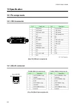
Page 88: ...GE 6 GREEN 7 WHITE BROWN Stripe 7 WHITE BROWN Stripe 8 BROWN 8 BROWN Fig 10 2 RJ 45 pin assignments Pin Signal name Pin Signal name 1 TMDS data2 16 Hot plug detect 2 TMDS data2 17 TMDS data0 3 TMDS da...

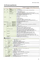
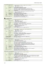
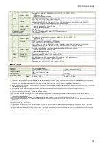
Page 89: ...8 Watts HDBaseT input scan converter output Max configuration About 387 Watts Fiber optic extension input scan converter output Max configuration About 418 Watts Dimensions 16 93 W x 8 66 H x 13 88 D...

Page 90: ...76p 720p 1080i 1080p VGA to QWXGA WUXGA QWXGA only support Reduced Blanking Audio Number Signal 4 outputs HDBaseT Multi channel linear PCM up to 8 channels Sampling frequency 32 kHz to 192 kHz Sample...

Page 91: ...onent are transmitted both inputs and outputs of this product When connected equipment is not matched to this product or other makers cables are used video signal can be unstable or video signals cann...

Page 92: ...setting of this device set to the input resolution supported by the sink device If the EDID resolution is set to 480i 576i or 1080i the video may not be output to the sink device that does not suppor...

Page 93: ...signals might have been degraded due to long haul transmission We have high quality cables cable boosters and extenders Please contact us as needed When high speed signals e g high resolution signals...

Page 94: ...If interlace signals are input to a sink device that does not support interlace signals the video may blink Check the output resolution of the sink device Video edges up down right left are cut out S...

Page 95: ...esult audio may not be output In that case set OUTPUT HDMI MODE to Always 49 Even though multi channel audio is played only audio signals of 2 channels are output For multiple channel play change the...

Page 96: ...is required please perform the following tests and then contact us 1 The problem occurs in all connectors 2 Connect the devices using genuine cables without connecting the FDX 32 The problem still ca...

Page 97: ...EL 1 203 204 2445 Email sales idkav com URL http www idkav com Europe IDK Europe GmbH Lise Meitner Str 6 D 40878 Ratingen TEL 49 2102 578 301 0 Email info idkav eu URL http www idkav eu Product inform...

Reviews: