MSD-501/502 Command Guide
8
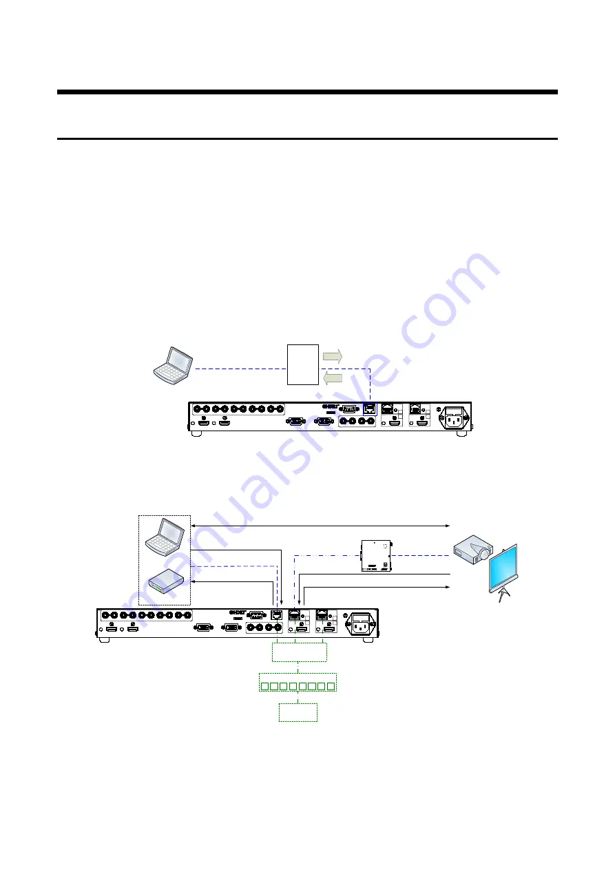
2.2 LAN communication
2.2.1 Setup LAN communication
(1) Connect the MSD and the control device via a LAN cable.
(2) Set up RS-232C communication as follows:
・
Set IP address and subnet mask
・
Operation mode of LAN communication: “RECEIVER”
・
TCP pot number: 23, 1100, 6000 to 6999
【
Reference: User’s Guide
】
(3) Establish the connection from the control device to the IP address and TCP port that are set to the
MSD in step (2) above.
(4) Send a communication command from the control device to the MSD in order to check the control
status of the MSD.
AC 100-240V 50Hz / 60Hz (FUSE T2.5A 250V)
FG
RS-232C
LAN
UPDATE
AUDIO OUT 2
AUDIO OUT 1
R
L
R
L
R
L
R
L
R
L
R
L
R
L
AUDIO IN 5
AUDIO IN 4
AUDIO IN 3
AUDIO IN 2
AUDIO IN 1
IN 3
HDMI / DVI
IN 2
HDMI / DVI
OUT 1
OUT 2
HDMI / DVI
HDMI / DVI
LINK
B
OUT 2
HDBaseT
LINK
B
OUT 1
HDBaseT
A
A
ANALOG RGB / YPbPr / VIDEO
IN 4
ANALOG RGB / YPbPr / VIDEO
IN 5
Step (2)
Step (1)
LAN cable
Step (4)
Step (3)
Laptop
Communi-
cation
command
[Fig. 2.4] Control via LAN communication
■
Operation example of LAN communication
Laptop
Projector
LAN cable
Twisted pair cable
LAN cable
Power amplifier
Communication command control to the MSD
Outputs control command to
external device
HDC series receiver
Switching hab
Communication command control to the MSD
Bidirectional communication
Control
device
1
2
3
4
5
6
7
8
AC 100-240V 50Hz / 60Hz (FUSE T2.5A 250V)
FG
RS-232C
LAN
UPDATE
AUDIO OUT 2
AUDIO OUT 1
R
L
R
L
R
L
R
L
R
L
R
L
R
L
AUDIO IN 5
AUDIO IN 4
AUDIO IN 3
AUDIO IN 2
AUDIO IN 1
IN 3
HDMI / DVI
IN 2
HDMI / DVI
OUT 1
OUT 2
HDMI / DVI
HDMI / DVI
LINK
B
OUT 2
HDBaseT
LINK
B
OUT 1
HDBaseT
A
A
ANALOG RGB / YPbPr / VIDEO
IN 4
ANALOG RGB / YPbPr / VIDEO
IN 5
Rx
R
S
-23
2C
L
AN
Cat6 Rx for HDMI
POWER
LINK
HDCP
STATUS
POWER
LINK
HDCP
POWER
LINK
HDCP
STATUS
FG
D
C
5V
2A
HDC-RH100-C
IN
P
UT
DON'T
CONNECT
LAN
H
DB
as
e
T
CAUTION
!
(MA
X
2
M)
H
DM
I
O
U
T
P
U
T
Connection
Outputs control command to external device
[Fig. 2.5] Sample application of LAN communication


