MSD-72 Series User’s Guide
122
■
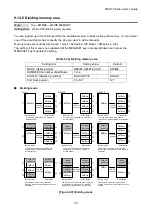
Displaying method
“BLOCK”
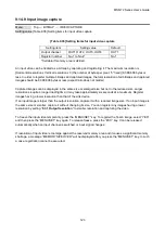
If you select “BLOCK” for “DISPLAY”, the current start and end block positions are displayed on the left of the
VFD screen. If a bitmap is registered, the final block position is displayed in parentheses. The start and end
block positions after divide are displayed on the right. If you want to specify the after-divide size directly,
change the end block position.
If the currently-registered bitmap is deleted because of specifying the size directly, an
“
S
”
or “E” is displayed
in the upper right.
“BYTE”
The currently-reserved memory size is displayed on the left. If a bitmap is registered, the number of bytes is
displayed in parentheses. The memory size after divide is displayed on the right so that you can specify
directly the after-division memory size.
If the currently-registered bitmap is deleted because of specifying the size directly, an “S” or “E” is displayed in
the upper right.
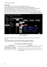
①
[BLOCK]
② ③
④ ⑤
①
Current block position
②
Current end block position
③
End block position of registered bitmap
The memory area is controlled by 1 block (=64 bytes) and end block position or size of the
bitmap is rounded up by 1 block.
④
Start block position after divide
⑤
End block position after divide
*1
*2
*1
⑥
[BYTE]
⑦
⑧
⑥
Current memory size
⑦
Memory size of registered bitmap
⑧
Memory size after divide
*1
※
2
The size can be specified directly.
*2
⑨
⑨
In case bitmap is deleted because of changing start
position of memory area, an
“
S
”
is displayed.
⑩
In case bitmap will be deleted because of changing
end position of the memory area, an
“
E
”
is
displayed.
⑩
[BITMAP1 BLOCK]
0- 63( 23) 0- 6
3
[BITMAP1 SIZE]
4194(1572)KB 419
4
KB
[BITMAP2 BLOCK]S
64-127(120) 60-10
3
[BITMAP2 BLOCK] E
64-127(120) 64-11
0
[Figure 9.32] “BLOCK” and “BITE”


