PDU-1209 User
’s Guide
12
4 Front and Rear Panels
①
③ ④
②
⑦
⑥
⑤
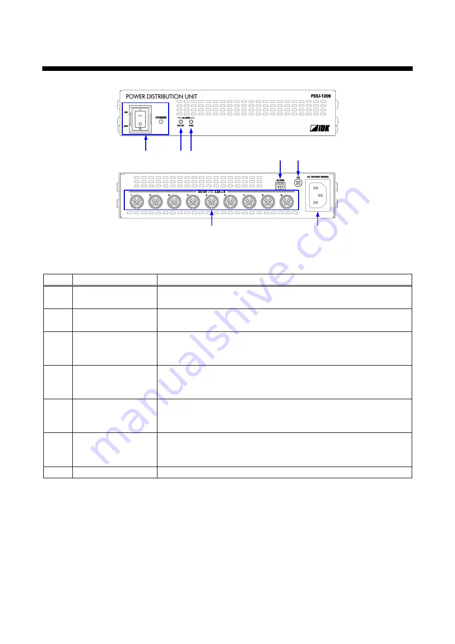
[Fig. 4.1] Panel drawing (Upper: Front panel, Lower: Rear panel)
[Table 4.1] Part names and descriptions
Number
Name
Description
①
POWER switch
Powers the PDU-1209 ON/OFF.
The POWER LED (green) lights when the PDU-1209 is powered on.
②
DC output connectors
Connects to target devices using DIN plug DC cables. When
①
is
turned ON, power is supplied to the target devices.
③
ALARM (DC12V) LED Illuminates red if an overcurrent condition causes one or more output
connectors (
②
) to be disabled.
【
See: 7 Alarm conditions
④
ALARM (FAN) LED
Illuminates red if the cooling fan fails to operate correctly
.
【
See: 7 Alarm conditions
⑤
ALARM connector
Detects abnormalities in the PDU-1209 power and its cooling fan using
the supplied 2-pin terminal block.
【
⑥
Frame ground
Ground terminal
⑥
can be used to provide an electrical bond between
the PDU-1209 and surrounding equipment ground potential.
An M4 screw is used.
⑦
AC power connector
For the supplied power cable


