72
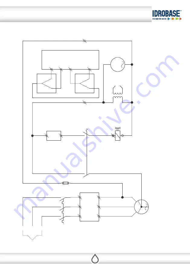
13 - DIAGRAM
5A
M
M
*
11
10
*
2
1
P2
P1
3
5
4
12
*
8
9
6
7
N
A
N
C
N
C
N
A
ELECTRIC SUPPLy
400 V
PUMP
MOTOR
BURNER
SOLENOID VALVE
IGNITION
TRANSFORMER
THERM OSTAT
BURNER
MOTOR
P1=PUMP PRESSURE SWITCH
P2=PRESSURE SWITCH
*=TOTAL STOP DEVICE
Cop
yrigh
t ©2016 I
dr
obase G
roup
. A
ll righ
ts r
eser
ved
.