Confidential Information - Do Not Distribute
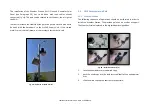
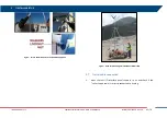
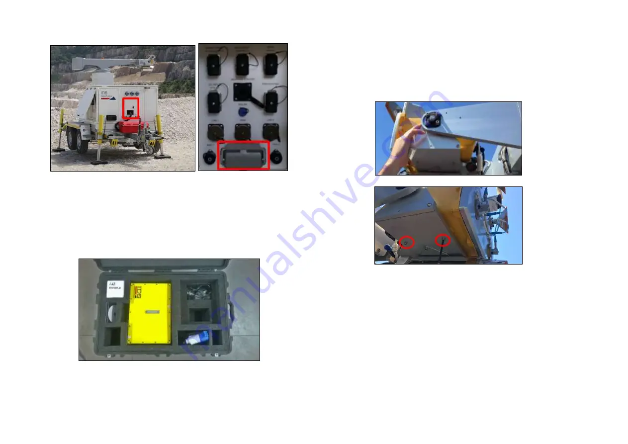
Fig. 94 – I/O Interfaces panel containing the Trailer Supply socket
5.8
IBIS Sensor Setup
For the first installation the Radar Sensor, with the 4 Antennas and the
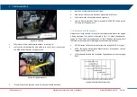
Pointing Camera already installed on it, is shipped in a big cardboard. (
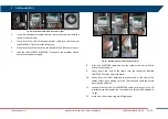
Fig. 95 – Radar Sensor case
To set correctly the Radar Sensor, follow the steps below:
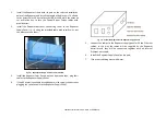
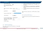
Fix the Radar Sensor on its support on the end of the positioner arm
by adjusting the center guide pivot of the sensor on its housing and
by screwing the 4 screws with the help of an allen key. (
Fig. 96 – Installing the Radar Sensor into its housing
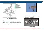
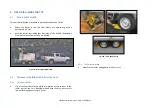
connect the Ethernet and Power Supply cable from to the Radar
Sensor. Screw together socket caps to prevent dust or water heap
(

